Stapler

A stapler and staple technology, applied in binding and other directions, can solve problems such as danger and achieve the effect of reducing operating force

Active Publication Date: 2009-07-15
KOKUYO CO LTD
View PDF0 Cites 4 Cited by
  • Summary
  • Abstract
  • Description
  • Claims
  • Application Information

AI Technical Summary

Problems solved by technology

[0006] However, for the stapler disclosed in Patent Document 1, since the structure is such that an intermediate piece is provided between each center portion of the operation frame and the handle, it is necessary to provide a space for the predetermined movement of the intermediate piece.
Therefore, when the handle is pressed, there is a gap where fingers and the like enter the space, causing danger.

Method used


Image

  • Stapler
  • Stapler
  • Stapler

Examples


Embodiment Construction

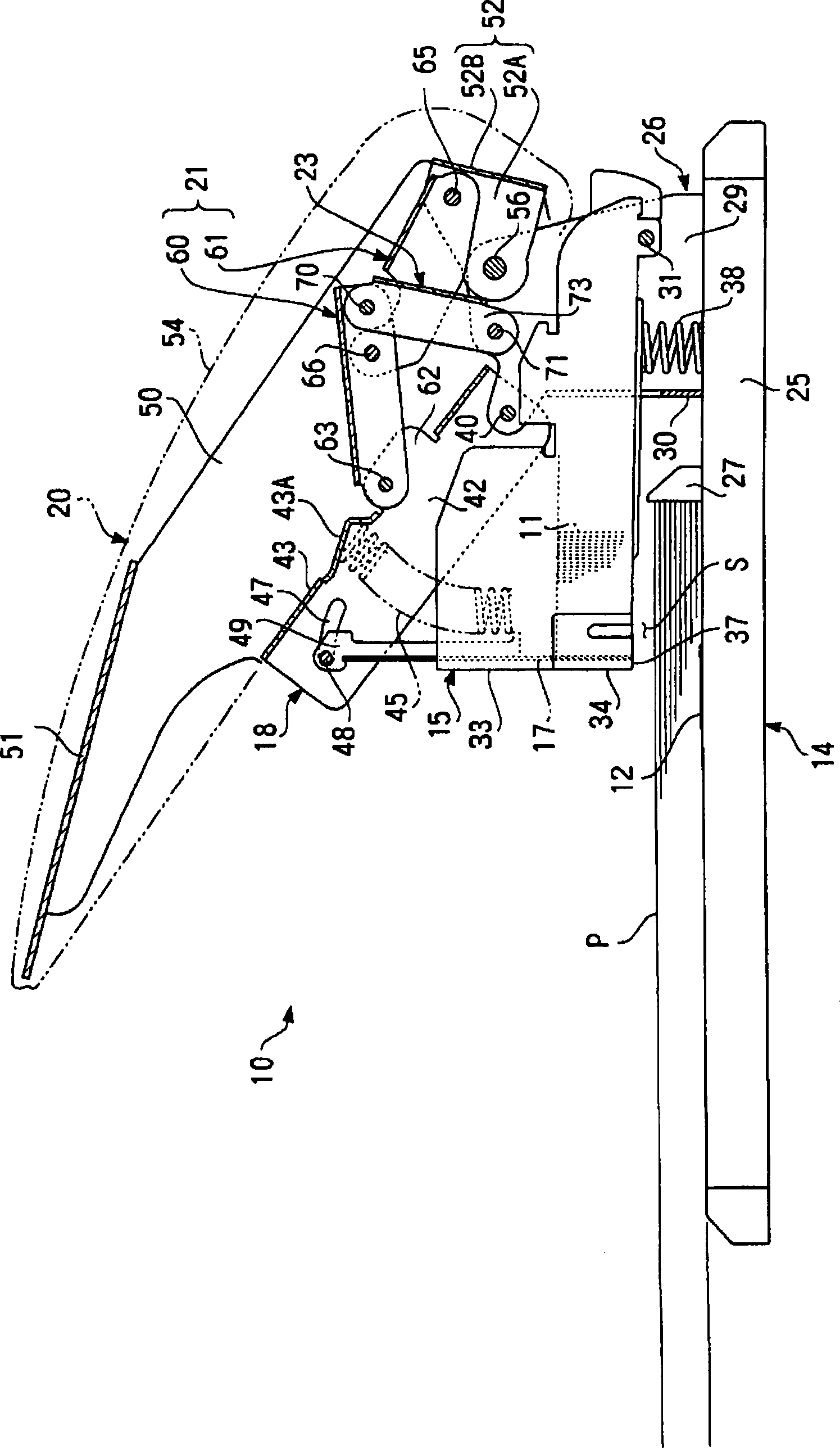
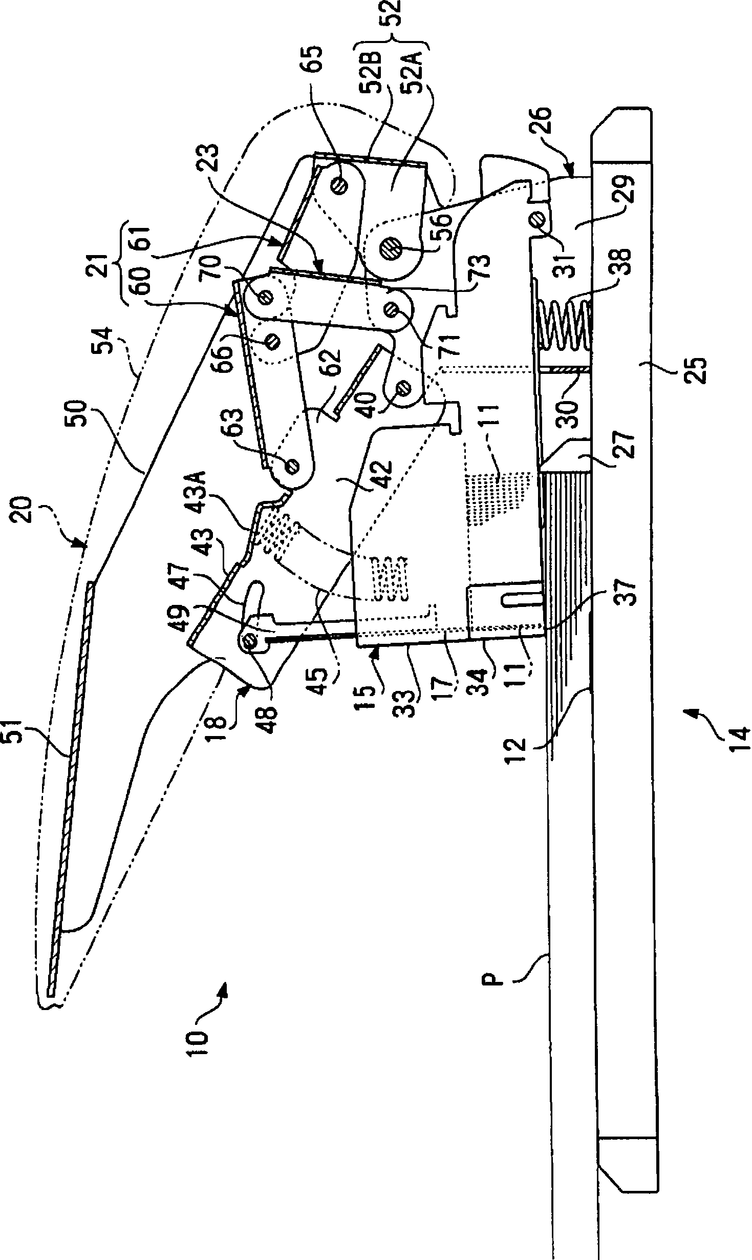
[0033] Hereinafter, preferred embodiments of the present invention will be described in detail with reference to the drawings. In addition, in this specification, terms indicating position or direction, unless otherwise specified, are referred to as figure 1 as the benchmark. Therefore, the so-called "former" is used to refer to figure 1 On the left side of the middle, the so-called "rear" is used to refer to the right side in the same figure.

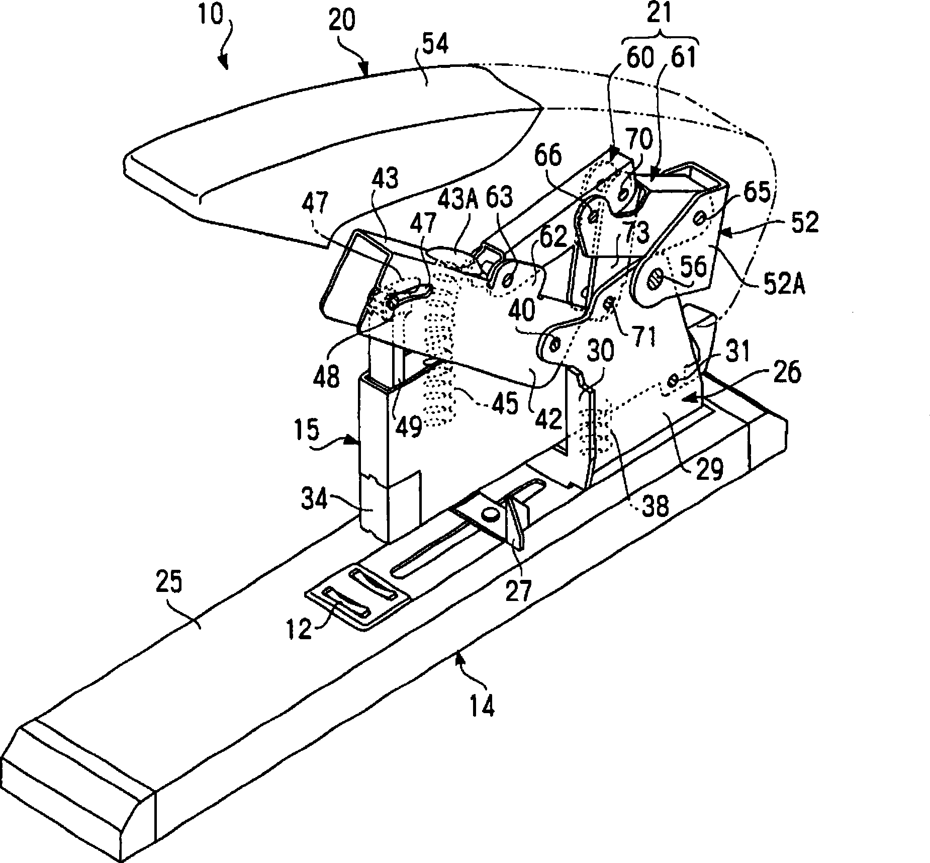
[0034] exist figure 1 , shows a schematic side view of the stapler of this embodiment, in figure 2 , a schematic perspective view thereof is shown. In these figures, the stapler 10 is constituted as having: a base 14 having an anvil 12 for nailing the staple 11; Between 12, an insertion space S is formed as the paper P of the binding object; an intermediate member 18 is rotatably supported by a base 14 and has a pressing blade 17 for pressing the above-mentioned staple 11 to the anvil 12; a handle 20, Its one end side is rotatab...


PUM


Abstract

The invention relates to a stapler, which does not form a space between the handle and the intermediate part, and can reliably alleviate the operating force. The stapler is provided with: a staple storage body (15) capable of rotary supporting the base (14); an intermediate part (18) having a pressure blade (17) capable of rotary supporting the base (14) and emitting the staples to the anvil stand (12); a handle (20) for pressing the intermediate part (18); an reinforcement mechanism (21) including a first and a second linkage rods( 60,61) between the handle (20) and the intermediate part (18); a support mechanism (23) composed of a third linkage rod (73) between the reinforcement mechanism (21) and the base (14), so that when a push operation is performed to the handle (20), a pressure is applied to the intermediate part (18) by the reinforcement mechanism (21) and the support mechanism (23).

Description

technical field [0001] The present invention relates to a stapler, and more specifically, to a stapler capable of reducing the operating force for driving a staple. Background technique [0002] Hitherto, a stapler (common name: stapler, hotchkiss) that binds a plurality of sheets of paper by driving a staple into them has been widely used. In addition to the portable type that can be accommodated in the palm of the hand, this stapler also has a large-scale installation type, and staples are driven by pressing the handle in a state where it is installed on a desk or the like. [0003] The latter setting type is used when the number of sheets of paper to be bound is large. Since a large operating force is required to drive the staples into the multiple sheets, a method with a reduced operating force has been proposed. Mechanism stapler (for example, refer to Patent Document 1). [0004] Patent Document 1: Patent No. 3900495 [0005] The staple mechanism disclosed in Patent...

Claims


Application Information

Patent Timeline
IPC IPC(8): B42B4/00
Inventor 兴津彰规
Owner KOKUYO CO LTD
Why Eureka
Try Eureka