Plasma deposition apparatus and method for making solar cells

A solar cell, plasma deposition technology, applied to circuits, electrical components, coatings, etc., to achieve high built-in potential, eliminate two-step process, and high throughput rate

Inactive Publication Date: 2009-07-08
SILICA TECH LLC +1
View PDF3 Cites 8 Cited by
  • Summary
  • Abstract
  • Description
  • Claims
  • Application Information

AI Technical Summary

Problems solved by technology

The combination of these steps inhibits an efficient fabrication process for making CIGS thin films

Method used


Image

  • Plasma deposition apparatus and method for making solar cells
  • Plasma deposition apparatus and method for making solar cells
  • Plasma deposition apparatus and method for making solar cells

Examples


Embodiment Construction

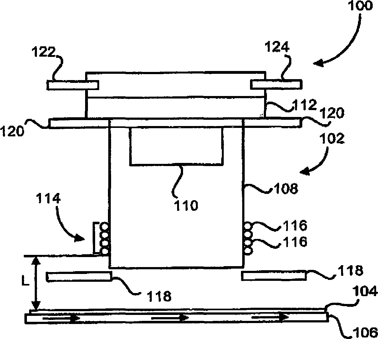
[0030] figure 1 An embodiment 100 of a plasma deposition apparatus including an inductively coupled plasma torch 102 positioned above a substrate 104 supported on a conveyor 106 is shown. In this embodiment, inductively coupled plasma torch 102 is aimed downward to deposit reaction products on substrate 104 . In another embodiment, the ICP torch 102 may be aimed or oriented in another manner or direction relative to the substrate 104 . The inductively coupled plasma torch 102 consists of two quartz tubes: an outer quartz tube 108 and a shorter inner quartz tube 110 , which are shown attached to a stainless steel chamber 112 .

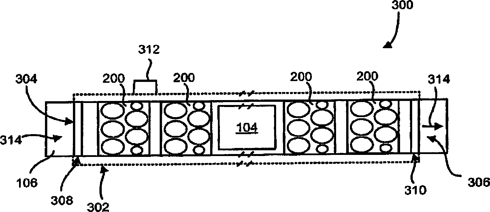
[0031] Conveyor 106 has a definition as with image 3 The longitudinal axis parallel to the direction of the arrow shown in . Conveyor 106 may be a fixed platform or a moving conveyor. Preferably, it provides support for one or several substrates 104 and presents these substrates to the ICP torch 102 at a desired distance depending on the ICP torch...


PUM

PropertyMeasurementUnit
diameteraaaaaaaaaa
diameteraaaaaaaaaa
diameteraaaaaaaaaa

Abstract

A plasma deposition apparatus for making solar cells comprising a conveyor having a longitudinal axis for supporting at least one substrate; at least two modules each having at least one plasma torch for depositing a layer of a reaction product on the at least one substrate, the at least one plasma torch located a distance from the at least one substrate; a chamber for containing the conveyor and the at least two modules; and an exhaust system. In another embodiment, the plasma deposition apparatus for making solar cells comprises: means for supporting a substrate; means for supplying reactants; plasma torch means for depositing a product on the substrate, the plasma torch means located a distance from the substrate; and means for oscillating the plasma torch means relative to the substrate.

Description

[0001] Related Application Cross Reference [0002] This application has the benefit of US Provisional Application 60 / 791883, filed April 14, 2006, and US Provisional Application 60 / 815575, filed June 22, 2006. The entire contents of these applications are incorporated herein by reference. technical field [0003] The invention relates to a process for making photovoltaic templates or solar cells. Background technique [0004] question [0005] As fuel prices have continued to rise, while other sources of energy remain limited, there is increasing pressure on global warming from emissions from burning fossil fuels. Alternative energy needs to be found and used, such as solar energy, because it is free and does not generate carbon dioxide gas. To this end, many countries are increasing their investment in safe and reliable long-term energy, especially "green" or "clean" energy. However, while solar cells, also known as photovoltaic cells or photovoltaic modules, have bee...

Claims


Application Information

Patent Timeline
Patent Type & Authority Applications(China)
IPC IPC(8): C23C16/507C23C16/54H01L31/20
Inventor 吴道M·A·阿斯拉米
Owner SILICA TECH LLC
Why Eureka
Try Eureka