
Radio frequency automatic test system for wireless communication base station

An automatic test system and wireless communication technology, applied in wireless communication, transmission system, transmission monitoring and other directions, can solve the problems of repeatability of faulty test results, high test cost, and high degree of uncertainty, and achieve a friendly interface and automation. The effect of a high degree and a full range of test types

Inactive Publication Date: 2009-07-08
TELECOMM METROLOGY CENT OF MINIST OF IND & INFORMATION TECH
View PDF3 Cites 39 Cited by
  • Summary
  • Abstract
  • Description
  • Claims
  • Application Information

AI Technical Summary

Problems solved by technology

[0003] For the RF test of base stations and repeaters, traditional methods often rely on manual connection to switch RF channels, or use standard program-controlled switch units produced by equipment suppliers such as Agilent, R&S, etc.; use manual connection to switch RF The shortcomings of the channel are obvious, that is, the test time is obviously prolonged, which is easy to cause human errors and the repeatability of the test results is not good; if the standard program-controlled switch unit is used to build the radio frequency unit of the base station repeater, its disadvantages are The complexity of the system is too high and the investment is huge, so that the test cost remains high; in addition, manual testing is easy to introduce some human error factors, and the test data results are closely related to the technical level, operation proficiency and subjective factors of the testers. high degree of certainty

Method used


Image

  • Radio frequency automatic test system for wireless communication base station
  • Radio frequency automatic test system for wireless communication base station
  • Radio frequency automatic test system for wireless communication base station

Examples


Embodiment Construction

[0040] The specific implementation manners of the present invention will be further described in detail below in conjunction with the accompanying drawings. It should be noted that the implementation of the wireless communication base station radio frequency automatic test system according to the present invention is only an example, but the present invention is not limited to this specific implementation.

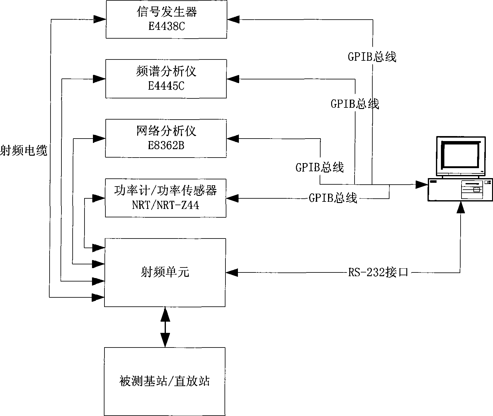
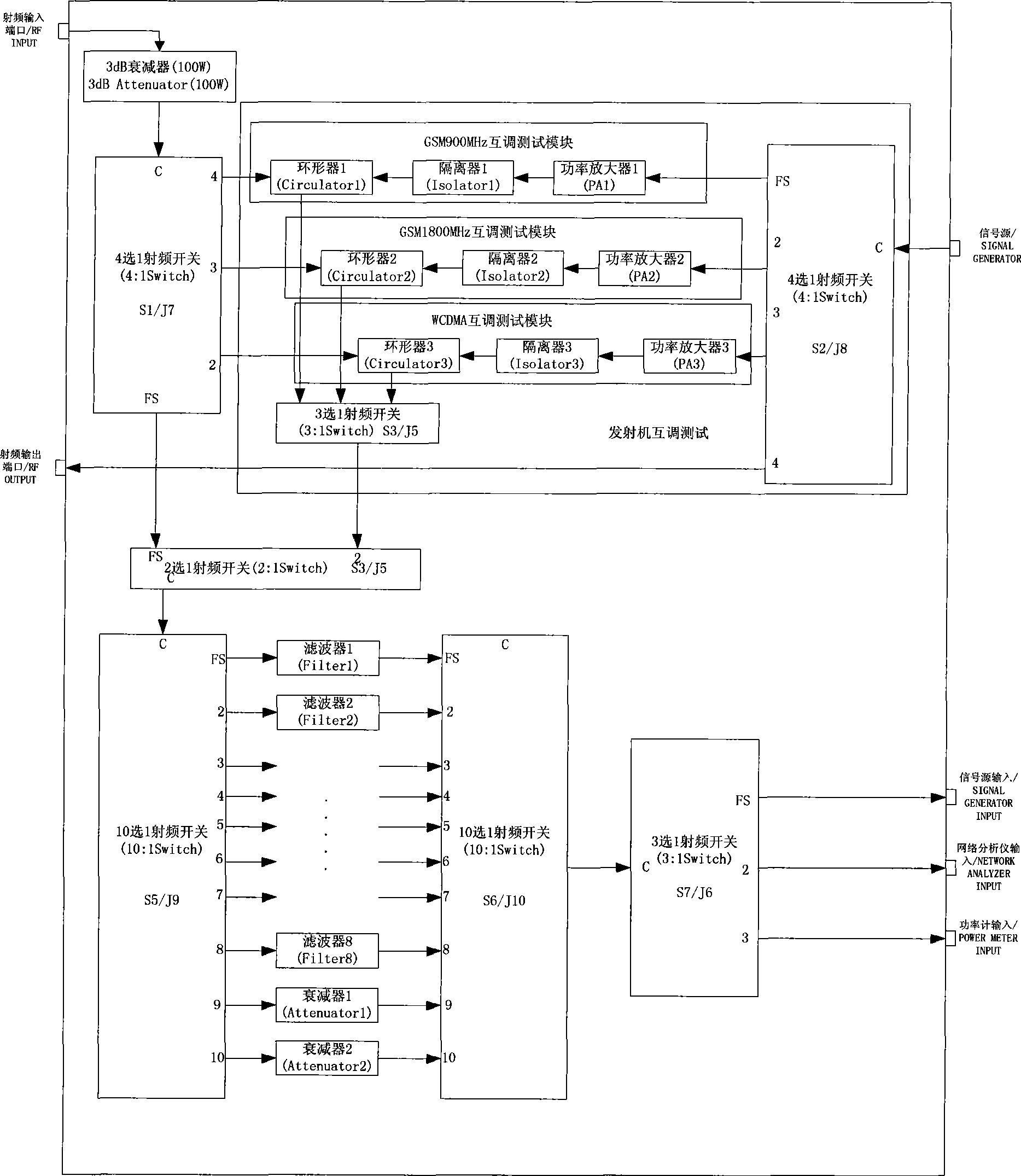
[0041] see figure 1 , the base station radio frequency automatic test system of the present invention is made up of spectrum analyzer, network analyzer, signal source, power meter, server that automatic test software is housed, radio frequency unit (by the filter of coaxial radio frequency switch and different specifications and attenuator) )constitute.

[0042] exist figure 1 Among them, the server loaded with the base station / repeater radio frequency test system software is the center of the automatic test system, and plays the role of controlling the test instrument a...


PUM


Abstract

The invention provides a base-station radio-frequency automatic test system which comprises a radio-frequency analyzer, a network analyzer, a signal source, a power meter, a severer equipped with automatic test software and a radio-frequency unit comprising coaxial radio-frequency switches as well as filters and attenuators of different specifications. The base-station radio-frequency automatic test system is arranged inside a large-size test cabinet. The operation of the system is under the centralized control of a high-performance workstation. The test software is designed to complete various base-station test items specified in the standard according to user's needs. The base-station radio-frequency automatic test system covers the whole range of the test of various radio-frequency parameters of base station of various communication systems, and maximizes the degree of test automation. Additionally, the base-station radio-frequency automatic test system has the advantages of wide coverage, full test types, high automation degree, easy operation, friendly interface, flexible configuration, convenience for updating along with the modification of the standard, automatic correction function, high test accuracy, and capability of networking several scattered labs via a local area network (LAN) and achieving the effect of test data sharing.

Description

technical field [0001] The present invention generally relates to a test system, and more specifically relates to a radio frequency automatic test system for a wireless communication base station. Background technique [0002] A base station (abbreviated BS) is a high-power multi-channel two-way radio transmitter fixed at a specific location. It is used for low-power channel two-way wireless communication such as mobile phones and mobile phones; the basic function of the repeater is a radio frequency power booster, a radio transmission relay device that enhances the signal during wireless communication transmission; In the mobile communication system, the repeater is located between the base station and the mobile station, and relays and transmits the two-way radio frequency signal between the two, which is used to fill the blind area covered by the base station or extend the coverage area. Unlike the base station, the repeater has no baseband processing circuit, does not d...

Claims


Application Information

Patent Timeline
Patent Type & Authority Applications(China)
IPC IPC(8): H04B17/00H04W24/00
Inventor 张睿吴镝陆冰松褚文华郭隆庆冉志强
Owner TELECOMM METROLOGY CENT OF MINIST OF IND & INFORMATION TECH
Learn More