Three-dimension graphics direct-writing method with multi-vision angle graphical input
A technology of three-dimensional graphics and graphic input, applied in the direction of instruments, etc., can solve the problems of high technical requirements for color three-dimensional holographic image production, difficult commercial application, harsh conditions, etc., and achieve the effect of flexible image input and processing.
- Summary
- Abstract
- Description
- Claims
- Application Information
AI Technical Summary
Problems solved by technology
Method used
Image
Examples
Embodiment 1
[0049] Embodiment one: see attached image 3 As shown, a three-dimensional graphics direct writing method for multi-view graphics input, the steps are as follows:
[0050] (1) To obtain the sub-viewpoint digital image of a three-dimensional object, it can be taken by a camera, with the object as the center, and taken at certain angles, or computer virtual three-dimensional image processing can be used to obtain the sub-viewpoint image of the virtual object. The image number is from 1 to n, and the image format is not limited.
[0051] (2) Perform red R, green G, and blue B color separation processing on each image, such as Figure 4 As shown, the numbers are R1, G1, B1, R2, G2, B2,..., Rn, Gn, Bn. If the obtained image is a grayscale image, this step can be omitted.
[0052] (3) Divide the above color-separated image to form sub-graphs, such as Figure 5 As shown, the size of each submap is m×m pixels. For example 64×64 pixels.
[0053] (4) if Figure 6 As shown, the fi...
Embodiment 2
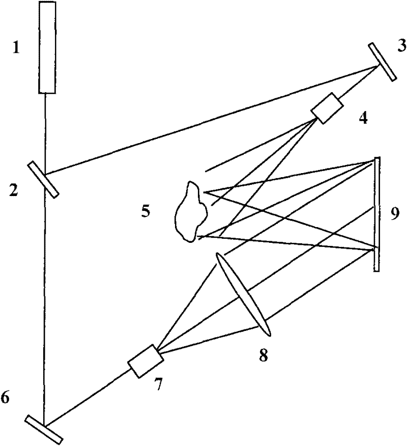
[0057] Embodiment two: see attached Figure 8 As shown, it is an optical path implementation method using an off-axis reflective spatial light modulator. The laser beam 71 passes through the beam splitter 72, and a beam of light is irradiated obliquely on the spatial light modulator 76 after beam expansion and collimation, and the information on the spatial light modulator is read out. The image of the object is reproduced, and the dry plate 78 is placed, and another beam of light passing through the beam splitter interferes with the object light wave on the dry plate 78 after proper beam expansion and collimation. The information on the spatial light modulator is controlled by the computer 712 in real time, and the dry plate and the optical system can move relative to each other in two dimensions within the plane of the dry plate to match the relative positions of the SLM and the dry plate to realize pattern splicing.
[0058] Compared with the traditional two-step method, t...
Embodiment 3
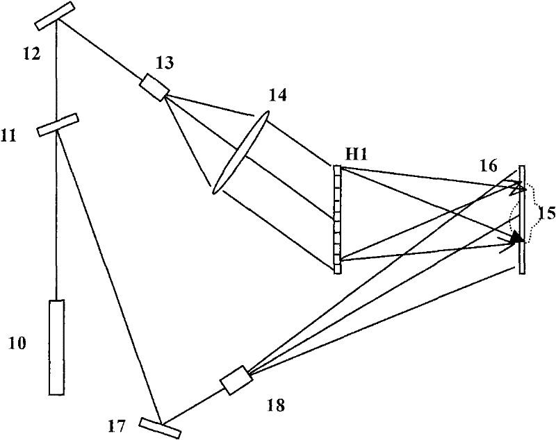
[0061] Embodiment three: see attached Figure 9 As shown, it is an optical path implementation method using a coaxial reflective spatial light modulator. After the laser beam 81 passes through the beam splitter 82, a beam of light is expanded and collimated, then irradiates the spatial light modulator 87 after passing through the beam splitter 86, reads information, and forms on the rear focal plane after passing through the Fourier transform lens 88 As for the image of the object, other processes are the same as in Embodiment 1.
PUM
 Abstract
Description
Claims
Application Information
 - Generate Ideas
- Intellectual Property
- Life Sciences
- Materials
- Tech Scout
- Unparalleled Data Quality
- Higher Quality Content
- 60% Fewer Hallucinations
Browse by: Latest US Patents, China's latest patents, Technical Efficacy Thesaurus, Application Domain, Technology Topic, Popular Technical Reports.
© 2025 PatSnap. All rights reserved.Legal|Privacy policy|Modern Slavery Act Transparency Statement|Sitemap|About US| Contact US: help@patsnap.com


