Optical actuator
A technology of optical actuators and optical components, which is applied in the direction of optics, optical components, instruments, etc., can solve the problems of product limitations and the inability to select optical actuators for different needs, so as to achieve commercialization and expand the scope of product applications Effect
- Summary
- Abstract
- Description
- Claims
- Application Information
AI Technical Summary
Problems solved by technology
Method used
Image
Examples
no. 1 example
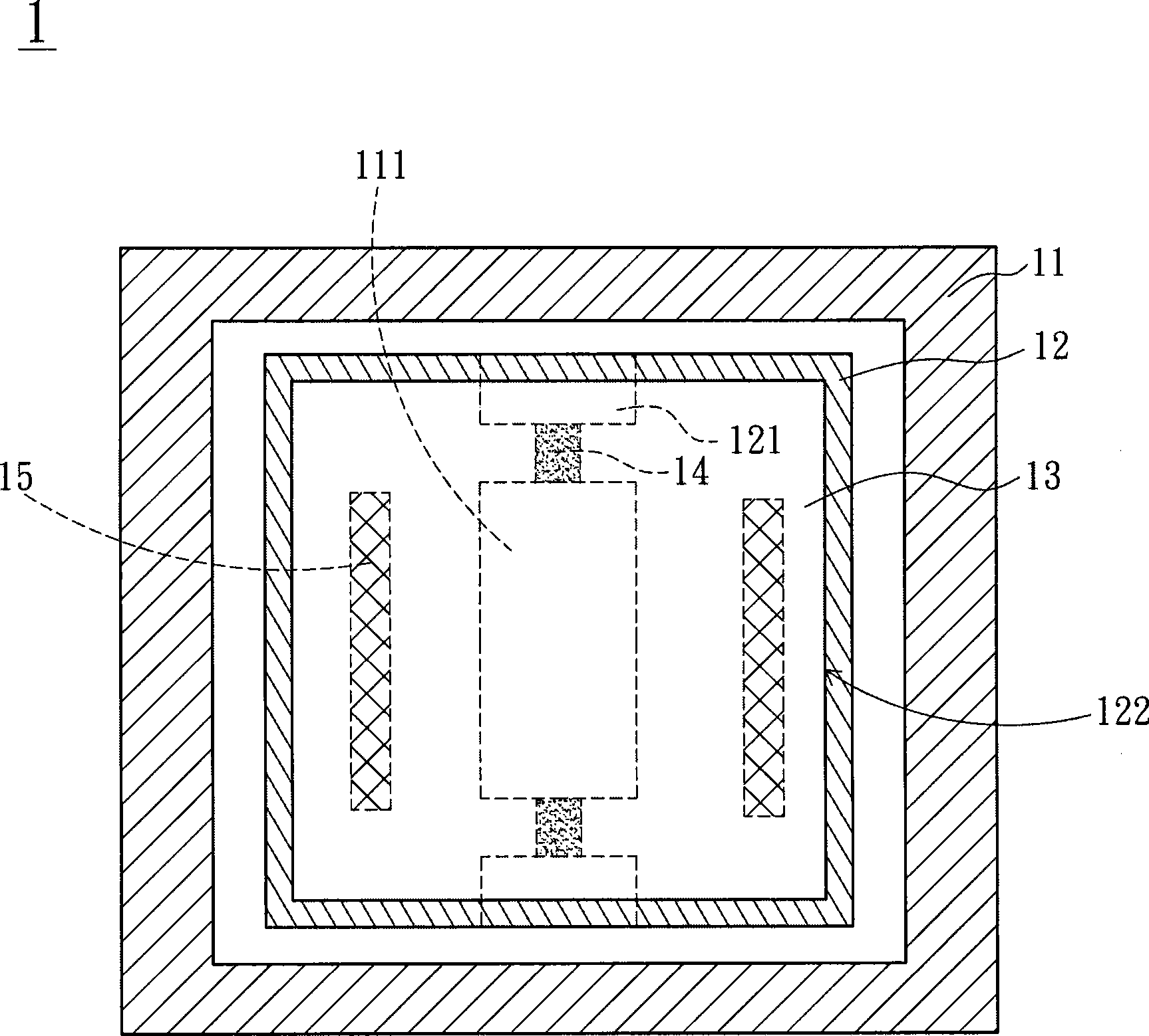
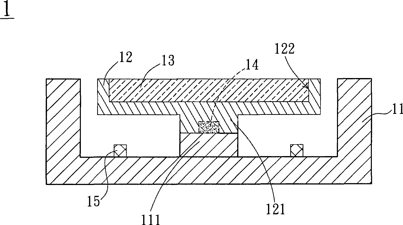
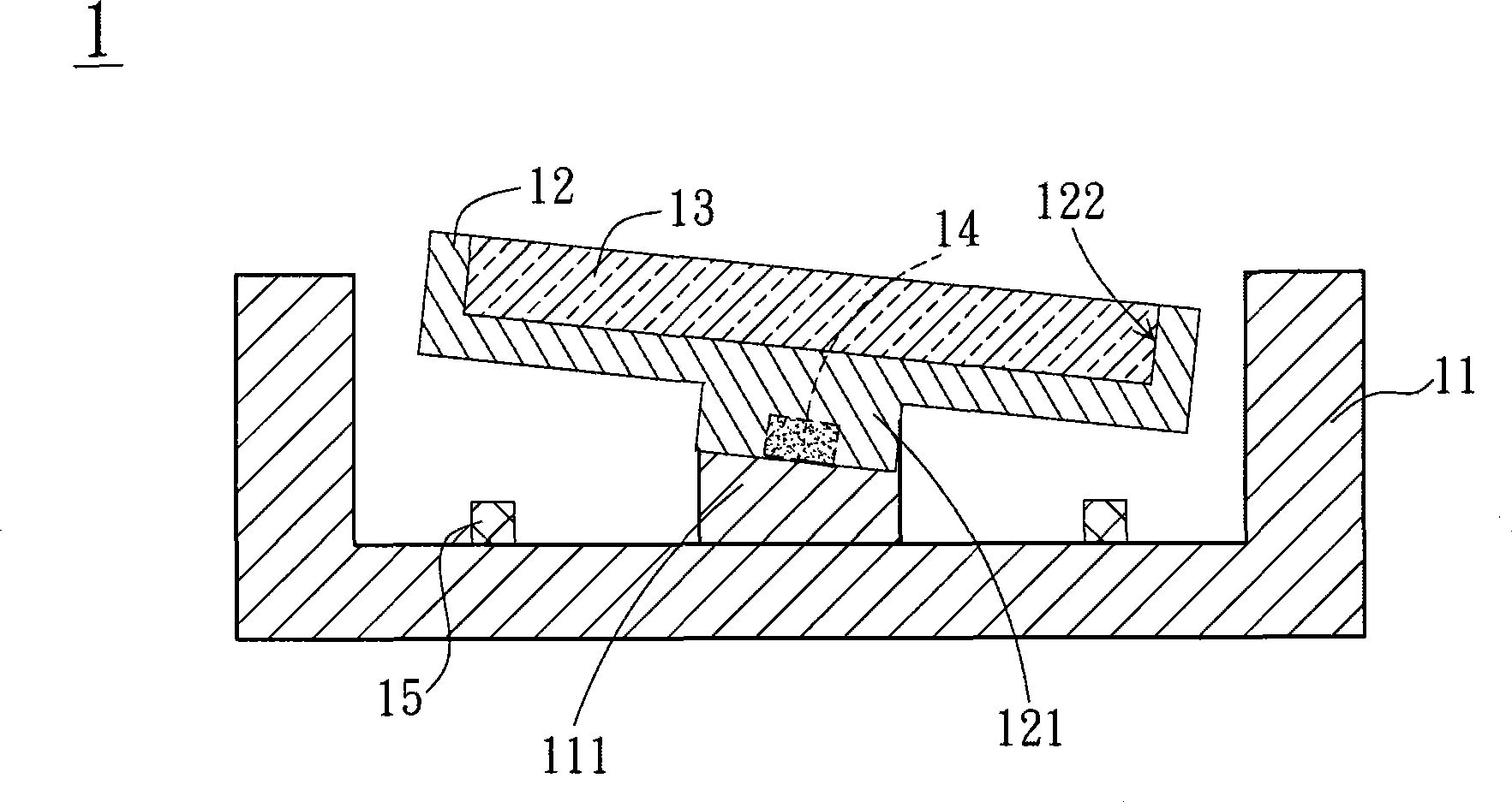
[0034] Please also refer to Figure 1A , Figure 1B and Figure 1C shown, where Figure 1A is a partial perspective view of the top surface of the optical actuator according to the first embodiment of the present invention, Figure 1B and Figure 1C for Figure 1A Schematic diagram of the action of the optical actuator.
[0035] The optical actuator 1 according to the first embodiment of the present invention includes a base 11 , a bearing seat 12 , an optical element 13 , two rotating structures 14 and two actuating components 15 . The carrying seat 12 is disposed in the base 11 , and the carrying seat 12 has an accommodating space 122 for accommodating the optical element 13 . Such as Figure 1B As shown, two actuating components 15 are disposed on the top surface of the base 11 and respectively located on two sides of a support portion 111 of the base 11 , which are used to drive the bearing base 12 to rotate the bearing base 12 at an angle. Here, the optical element 1...
no. 2 example
[0039] Please also refer to Figure 2A and Figure 2B , Figure 2A is a top perspective view of an optical actuator according to a second embodiment of the present invention, Figure 2B and Figure 2C for Figure 2A Schematic diagram of the action of the optical actuator. The optical actuator 2 of the second embodiment of the present invention includes a base 21 , a bearing seat 22 , an optical element 23 , two rotating structures 24 and an actuating component 25 . Two first protrusions 221 extend downwards from the bottom of the bearing seat 22, and a support portion 211 is further provided on the base 21, and the two first protrusions 221 are connected to the base through two rotating structures 24 respectively. A support portion 211 of the seat 21 is connected. However, the difference from the first embodiment is that the rotating structure 24 is disposed on the top surface of the support portion 211 , and when the actuating assembly 25 operates, the supporting seat 2...
no. 3 example
[0042] In addition, the present invention can also be applied to a transmissive optical actuator. Please also refer to Figure 3A and Figure 3B , Figure 3A is a top perspective view of an optical actuator according to a third embodiment of the present invention, Figure 3B for Figure 3A side view of the optical actuator. The optical actuator 3 of the first embodiment of the present invention includes a base 31 , a bearing seat 32 , an optical element 33 , two rotating structures 34 and two actuating components 35 . In this embodiment, the base 31 and the bearing seat 32 are a frame structure, wherein the bearing base 32 is disposed in a through hole 312 of the base 31, and the bearing base 32 has an opening 322 for accommodating optical elements 33 , and the two actuating components 35 are respectively provided on both sides of the base 31 and located in the through hole 312 to drive the bearing seat 32 to rotate the bearing seat 32 at an angle. Here, the optical elem...
PUM
 Abstract
Description
Claims
Application Information
 - R&D Engineer
- R&D Manager
- IP Professional
- Industry Leading Data Capabilities
- Powerful AI technology
- Patent DNA Extraction
Browse by: Latest US Patents, China's latest patents, Technical Efficacy Thesaurus, Application Domain, Technology Topic, Popular Technical Reports.
© 2024 PatSnap. All rights reserved.Legal|Privacy policy|Modern Slavery Act Transparency Statement|Sitemap|About US| Contact US: help@patsnap.com


