
Air valve pressing mechanism capable of precisely controlling different air valve angle shift-down

A technology of precise control and pressing mechanism, applied in the direction of internal combustion engine test, engine test, machine/structural component test, etc., can solve the problems of difficult displacement control, difficult to fix displacement sensor, complex structure, etc

Active Publication Date: 2009-07-08
TIANJIN UNIV
View PDF0 Cites 4 Cited by
  • Summary
  • Abstract
  • Description
  • Claims
  • Application Information

AI Technical Summary

Problems solved by technology

The disadvantage of this method is that there is no installation position at the valve of the cylinder head. In addition to the displacement sensor being difficult to fix, the measuring head of the sensor is also difficult to contact with the valve.
Similar to the first method, the initial position of the valve lift depends on the hand feel, and the zero point judgment is extremely inaccurate
Moreover, the use of stepping motors and worm gear mechanisms causes complex structures, and excessive transmission makes displacement control more difficult

Method used


Image

  • Air valve pressing mechanism capable of precisely controlling different air valve angle shift-down
  • Air valve pressing mechanism capable of precisely controlling different air valve angle shift-down
  • Air valve pressing mechanism capable of precisely controlling different air valve angle shift-down

Examples


Embodiment

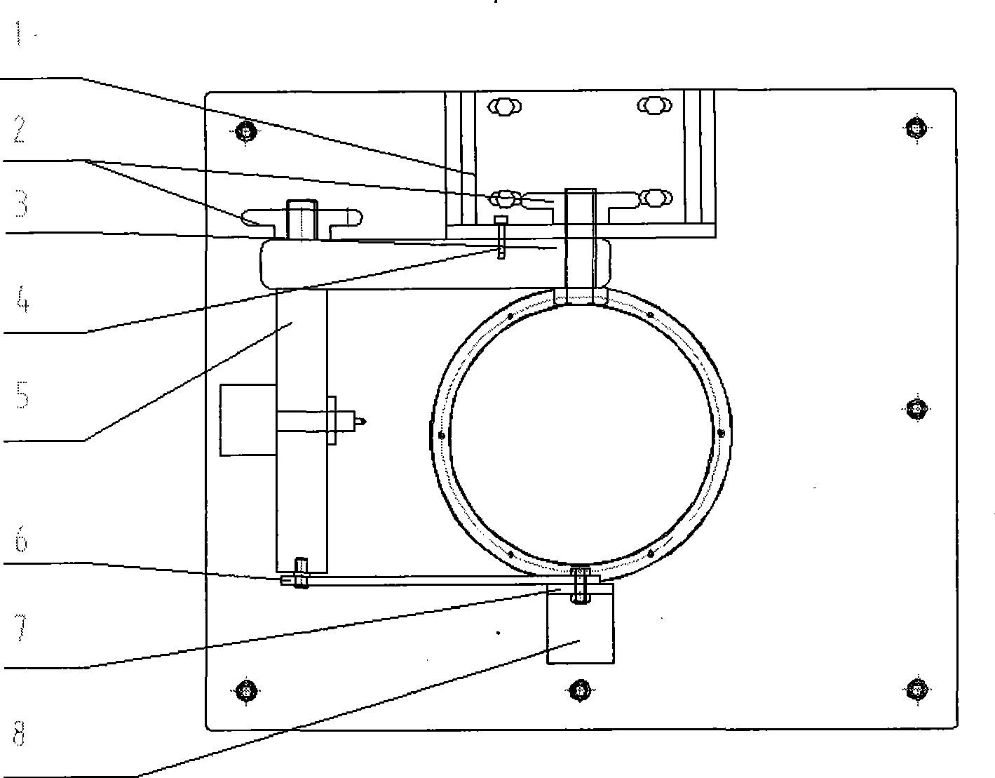
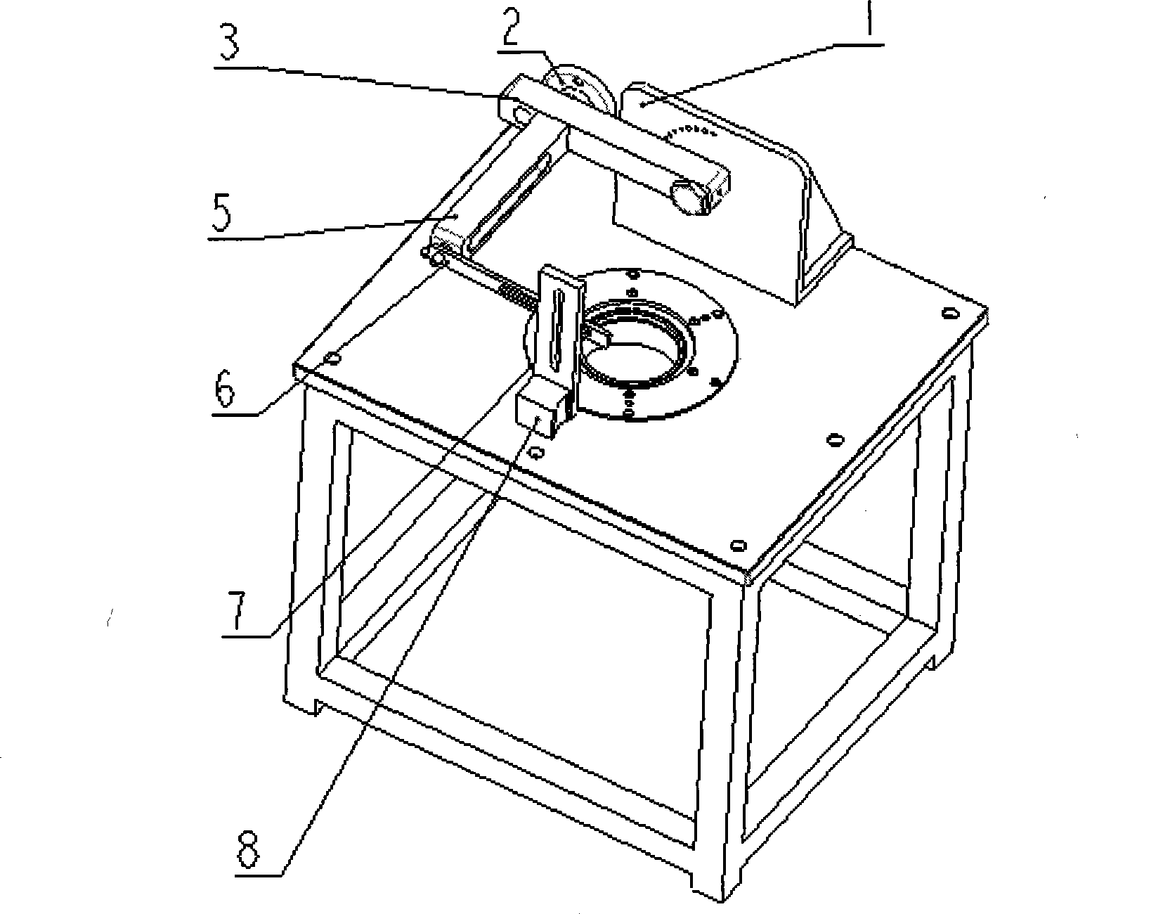
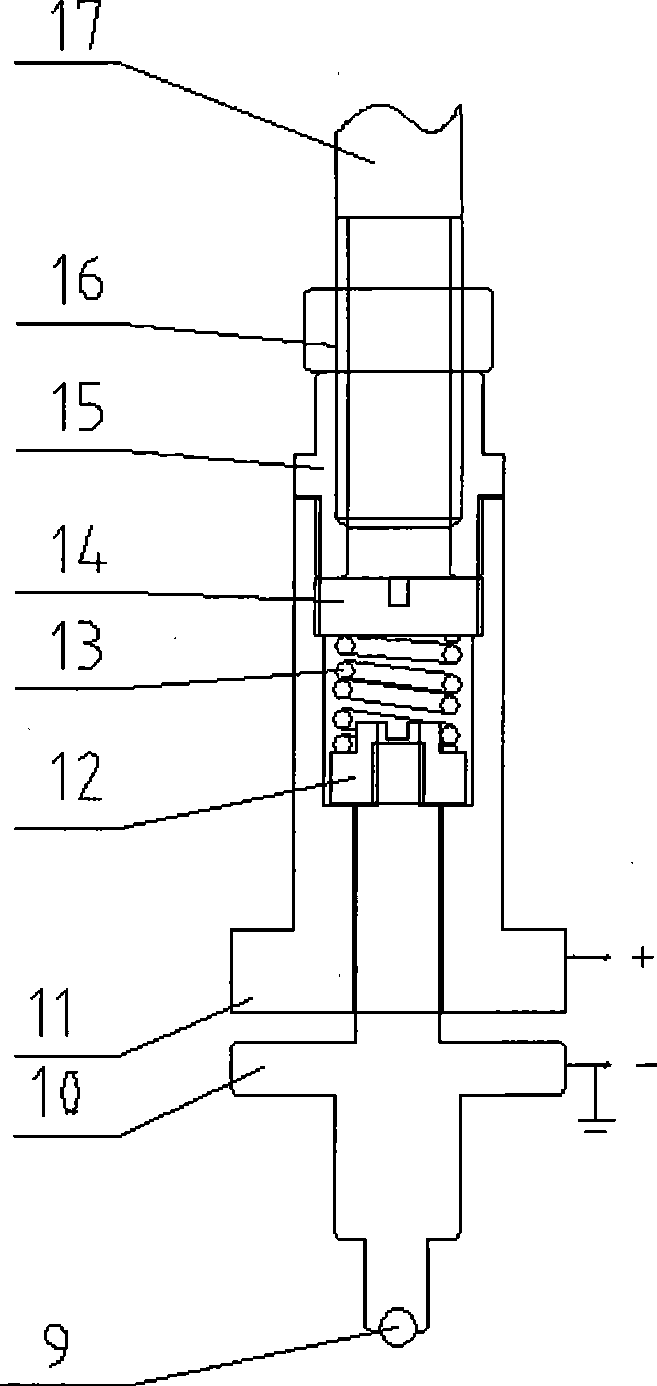
[0013] Embodiment: The cylinder head of the internal combustion engine is placed on the airway test bench, and the vertical arm 3 and the cross arm 5 are rotated and adjusted so that the spherical indenter 9 can be vertically pressed into the valve, and then the vertical arm and the vertical plate shaft are fixed with bolts and locking wheels , and at the same time use the positioning pin 4 to place the small hole on the vertical plate 1 ( image 3 ) is connected with the arc groove on the vertical arm. The linear motor is controlled by a computer. When the detection assembly presses the valve downward through the extension shaft of the linear motor, the spherical pressure head 9 remains stationary due to the certain rigidity of the valve spring in the cylinder head of the internal combustion engine, so the upper end surface of the connector is also Keep it still, and the detection piece moves downward. When the spring 13 in the detection assembly is fully compressed, that is,...


PUM


Abstract

The invention discloses a valve pressing mechanism of a cylinder cover of a test bench for detecting flow property of an air passage of an internal combustion machine. The valve pressing mechanism mainly comprises two parts of a frame component and a detection component. A frame component structure comprises that: a vertical plate is fixed on the plane of the test bench by a locking wheel; and a vertical arm is connected with a vertical plate shaft. Two ends of a transverse arm are fixed with the vertical arm and a locking wheel of a supporting rod respectively. The supporting arm is fixed on a magnetic seat; and the magnetic seat is fixed on the plane of the test bench. A detection component structure comprises that: a spherical pressure head is fixed with the lower end of a socket connector which is inserted into an inner cavity of the detection component. The upper end of the socket connector is fastened with a spring seat by screw thread. A spring is pressed into the inner cavity of the detection component; and the top end of an extending shaft of a linear motor and a shaft sleeve are fixedly connected and are locked by lock nuts. The detection component is assembled in the middle position of the transverse arm. The valve pressing mechanism has the characteristics that the valve pressing mechanism can meet the test of the air passages of the cylinder covers with various valve slope angles through angle adjustment of the vertical arm, ensure that the pressure head can be vertically pressed into the valve, realize the zero judgment of the lift range of the engine valve and the precise control of the lift range and improve detection precision.

Description

technical field [0001] The invention belongs to the detection technology of performance parameters of an internal combustion engine, and in particular relates to a cylinder head valve pressing mechanism on a test bench for the detection of flow performance of an internal combustion engine air passage. technical background [0002] The flow performance steady flow test bench of the internal combustion engine air passage can measure the flow coefficient, swirl ratio, tumble ratio and other flow parameters of the engine cylinder head intake passage. In order to obtain good power, economy and emission characteristics of the engine, the cylinder head of the engine must have a sufficiently high flow coefficient and appropriate swirl ratio, tumble ratio and other parameters. Therefore, this test bench has always been an important part of engine quality inspection. tool. However, the detection of the airway performance of the engine by the airway test bench involves multidisciplina...

Claims


Application Information

Patent Timeline
IPC IPC(8): G01M15/05G01M15/02
Inventor 王天友刘书亮鲁祯方学飞詹仰钦王刚德
Owner TIANJIN UNIV
Learn More