
Mold for shaping middle part of cross member

A technology for forming molds and cross bars, which is applied in the field of forming molds in the middle of cross bars, can solve problems such as easy deviation of workpiece positioning, easy changes in precision, and reduced work efficiency.

Inactive Publication Date: 2009-07-08
CRRC QIQIHAR ROLLING CO LTD +1
View PDF0 Cites 12 Cited by
  • Summary
  • Abstract
  • Description
  • Claims
  • Application Information

AI Technical Summary

Problems solved by technology

[0005] In the above device, since each positioning of the workpiece is realized by the movable die, when the diameter of the workpiece fluctuates, the oblique device is worn, or the reset position of the movable die changes, the positioning of the workpiece is prone to deviation. The axis of the workpiece and the longitudinal centerline of the punch cannot coincide in the vertical plane, which is prone to eccentric quality problems
Especially when mass production is carried out, the die is subject to frequent stamping, and the precision is prone to change. Frequent repairs are required to ensure the precision of the die, which reduces work efficiency

Method used


Image

  • Mold for shaping middle part of cross member
  • Mold for shaping middle part of cross member
  • Mold for shaping middle part of cross member

Examples


Embodiment Construction

[0026] In order to further understand the present invention, the preferred embodiments of the present invention are described below in conjunction with the examples, but it should be understood that these descriptions are only to further illustrate the features and advantages of the present invention, rather than limiting the claims of the present invention.

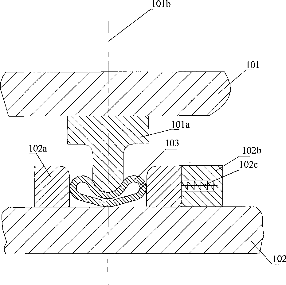
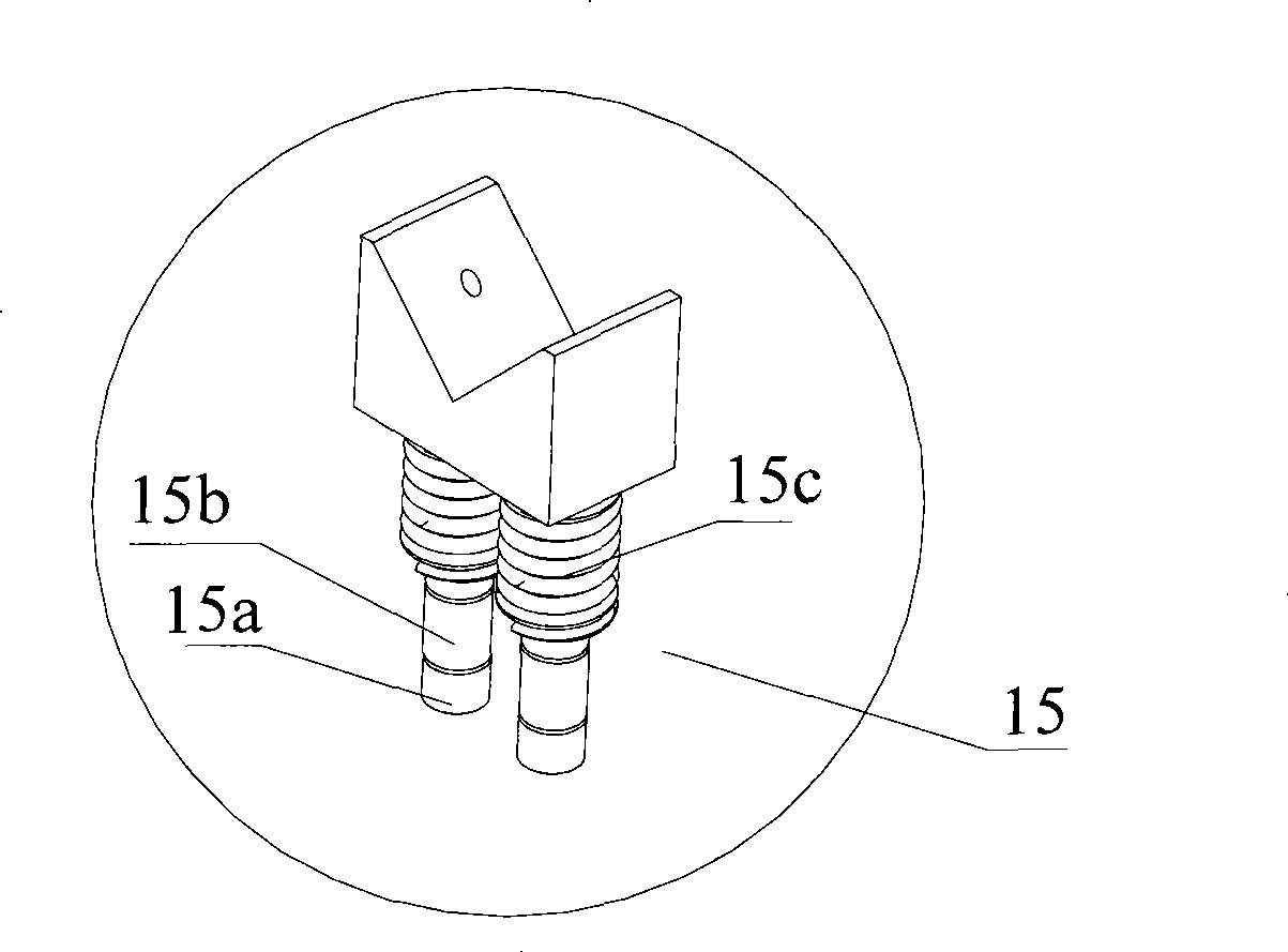
[0027] See figure 2 and image 3 As shown, it is a schematic diagram of a specific embodiment of the cross bar middle forming die provided by the present invention, figure 2 The exploded schematic diagram of the lower mold of the cross bar middle forming mold provided by the present invention, image 3 It is an overall disassembled schematic diagram of the forming mold for the middle part of the cross bar provided by the present invention. like figure 2 As shown, in the forming mold, a lower template 1 connected with a hydraulic device is included, and a lower mold base 12 is fixedly installed on the lower template...


PUM


Abstract

The invention discloses a cross rod middle forming die. The forming die comprises: a convex die which is used for punch forming, wherein, the convex die is fixedly arranged on an upper die plate by an upper die holder; a concave die which is matched with the convex die, wherein, the concave die is fixedly arranged on a lower die plate by a lower die holder; and a pair of liftable follow-up positioning devices which are used for positioning a workpiece to cause the axis of the workpiece and the longitudinal center line of the concave die to be kept at the same vertical plane, wherein, the pair of the positioning devices are respectively arranged at two ends of the concave die. The axis of the workpiece is automatically kept at the same vertical plane with the longitudinal center line of the concave die when the workpiece is placed on the positioning devices before forming, and the convex die moves downwards along with the upper die plate to form the workpiece, which can avoid the quality problems that the eccentric centers and microcracks and the like are formed in the workpiece forming, and improve the fatigue property of a cross fabrication device.

Description

technical field [0001] The invention relates to a mold, in particular to a mold for forming the middle part of a cross bar. Background technique [0002] The cross bracing device of a railway vehicle is an important part of the bogie, and the reliability of the cross bracing device directly affects the running stability and safety of the railway vehicle. The cross bar is the main part of the cross support device. The middle part of the cross bar is a nest-like structure formed by thick-walled tubes deformed with large curvature. The nest-like structure is assembled with fasteners and elastic bodies to form the cross support device of the transition frame. [0003] During the operation of the vehicle, the cross-bracing device is always subjected to alternating dynamic loads, so it is required to have good fatigue resistance. Since the dimple structure in the middle of the cross bar is an important structure that affects the performance of the cross support device, there are ...

Claims


Application Information

Patent Timeline
IPC IPC(8): B21D37/10B21D37/12B21D37/01B61F5/02
Inventor 张瑞喜李信义朱广庆
Owner CRRC QIQIHAR ROLLING CO LTD
Learn More