
DC-DC decompression converter and ripple improving circuit

A DC step-down and converter technology, which is applied in the direction of DC power input conversion to DC power output, output power conversion devices, instruments, etc., can solve the problem of high cost, achieve simple structure, reduce cost, and achieve convenient effects

Inactive Publication Date: 2010-10-20
赵丽娟 +4
View PDF5 Cites 0 Cited by
  • Summary
  • Abstract
  • Description
  • Claims
  • Application Information

AI Technical Summary

Problems solved by technology

[0009] The purpose of the present invention is to provide a DC-to-DC step-down converter to solve the problem of high cost in the ripple reduction method of the DC-to-DC step-down conversion circuit in the prior art
[0010] Another object of the present invention is to provide a ripple improvement circuit to solve the problem of high cost in the ripple reduction method of DC to DC step-down conversion circuit in the prior art

Method used


Image

  • DC-DC decompression converter and ripple improving circuit
  • DC-DC decompression converter and ripple improving circuit
  • DC-DC decompression converter and ripple improving circuit

Examples

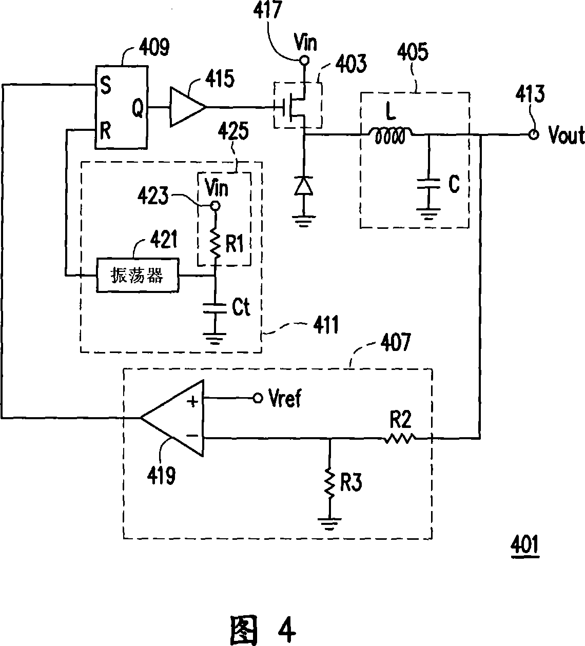

Embodiment Construction

[0024] The present invention will be described in detail below in conjunction with the accompanying drawings.

[0025] The present invention proposes a novel feedforward method, which can achieve the purpose of reducing the output ripple (ripple) of the DC-to-DC step-down converter 401 by adjusting the maximum duty ratio to an appropriate value.

[0026] See Figure 4 , which is a circuit diagram of a DC-to-DC step-down converter according to an embodiment of the present invention.

[0027] The DC-to-DC step-down converter 401 is used to convert the input voltage to a lower output voltage. The DC-to-DC buck converter 401 includes a switch 403 , a filter circuit 405 , a comparison circuit 407 , a flip-flop 409 and a reset signal generating circuit 411 . The switch 403 is respectively connected to the input terminal 417 and the filter circuit 405, Figure 4 The middle switch 403 is a field effect transistor. The filter circuit 405 is connected to the output terminal 413 , an...


PUM


Abstract

The invention provides a DC-DC buck converter and a ripple improving circuit thereof. The DC-DC buck converter is used for converting the input voltage to the lower output voltage and comprises a switch for controlling the turning-on and the turning-off states of a path between the input voltage and the output voltage, a filter circuit for enabling the output voltage to trend to be stable, a comparison circuit for outputting a set signal according to the output voltage, a reset signal generating circuit for generating a reset signal and a trigger for controlling the starting and the closing states of the switch according to the set signal and the reset signal. The reset signal generating circuit comprises an oscillator, a capacitor which is externally connected to the oscillator, and the ripple improving circuit. The ripple improving circuit comprises a power supply input terminal for providing the voltage and a resistor with one end which is connected with the oscillator and the capacitor and the other end which is connected with the power supply input terminal. The invention is used for regulating the time for charging the capacitor, further adjusts the maximum duty cycle of thereset signal and improves the output ripple of the buck converter.

Description

technical field [0001] The invention relates to a DC-to-DC step-down converter and a ripple improvement circuit thereof, in particular to a DC-to-DC step-down converter capable of improving output ripple and a ripple improvement circuit thereof. Background technique [0002] Today's electronic products have higher and higher requirements for operating voltage, and some commonly used power supply voltages can no longer meet the requirements of many electronic products. In the current power supply design, more and more voltage conversion circuits are used. For example, when the power supply voltage is based on the central processing unit (CPU), DIMM (Dual Inline Memory Module, dual inline memory module), etc., it is often necessary to convert the input voltage of the power supply to an output voltage suitable for the load to make the load normal work. [0003] In a DC-to-DC step-down conversion circuit (BUCK circuit) that uses a combination of a comparator and an RS flip-flo...

Claims


Application Information

Patent Timeline
Patent Type & Authority Patents(China)
IPC IPC(8): H02M3/155H02M3/156H02M1/14
Inventor 夏春华刘士豪
Owner 赵丽娟
Learn More