Centring type rotary plunger oil-well pump

A technology of oil well pump and rotary column, which is applied in the field of centering rotary plunger oil well pump, can solve the problems of oil production accident shutdown loss, low actual benefit of oil field, little improvement of pump barrel friction, etc., and achieve reduction of oil production cost, The effect of lightening the load and reducing the number of operations

Inactive Publication Date: 2010-12-08
姚尔强 +1
View PDF4 Cites 0 Cited by
  • Summary
  • Abstract
  • Description
  • Claims
  • Application Information

AI Technical Summary

Problems solved by technology

Although the structure is simple, there are many disadvantages: when working, the plunger moves up or down under the pull of the sucker rod. Due to the relatively large friction force of the plunger on the pump barrel, there is also the problem that the plunger hits the fixed valve. Not only the plunger The directional wear of the plug on the pump barrel is relatively large, and the working efficiency is naturally low. It is also prone to sand sticking and rod breakage, etc., resulting in frequent accidents in oil production operations and loss of production stoppage. The actual benefit is not high
[0003] In order to solve the above problems, the inventor once designed a kind of "self-rotating plunger oil well pump" (patent number: 02257356.9), a universal rotator is connected at the end of the plunger; The propeller thruster of the torque line groove, when working, the plunger is driven to rotate by means of the universal rotator and the propeller thruster under the impact of the oil flow, which relatively improves the ability of the plunger to rotate and run, but due to the impact of the plunger on the pump barrel The friction has not improved much, so there are still problems such as low working efficiency, sand stuck, and directional wear

Method used


Image

  • Centring type rotary plunger oil-well pump
  • Centring type rotary plunger oil-well pump
  • Centring type rotary plunger oil-well pump

Examples


Embodiment Construction

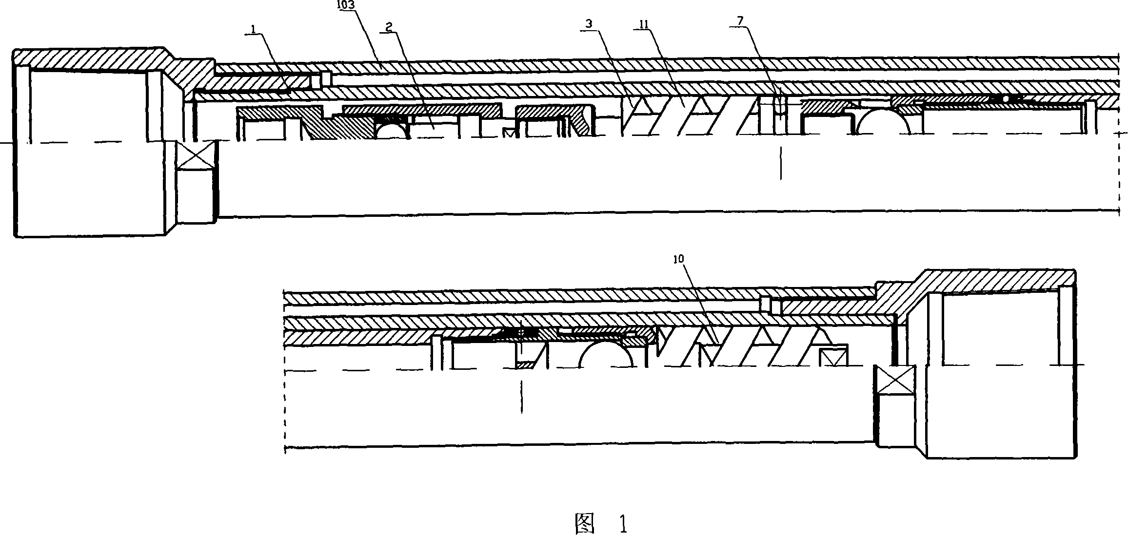
[0033] like figure 1 As shown, the overall structure of the centering rotary plunger oil pump of the present invention includes three parts: a pump barrel unit, a plunger unit, and a spinner unit.

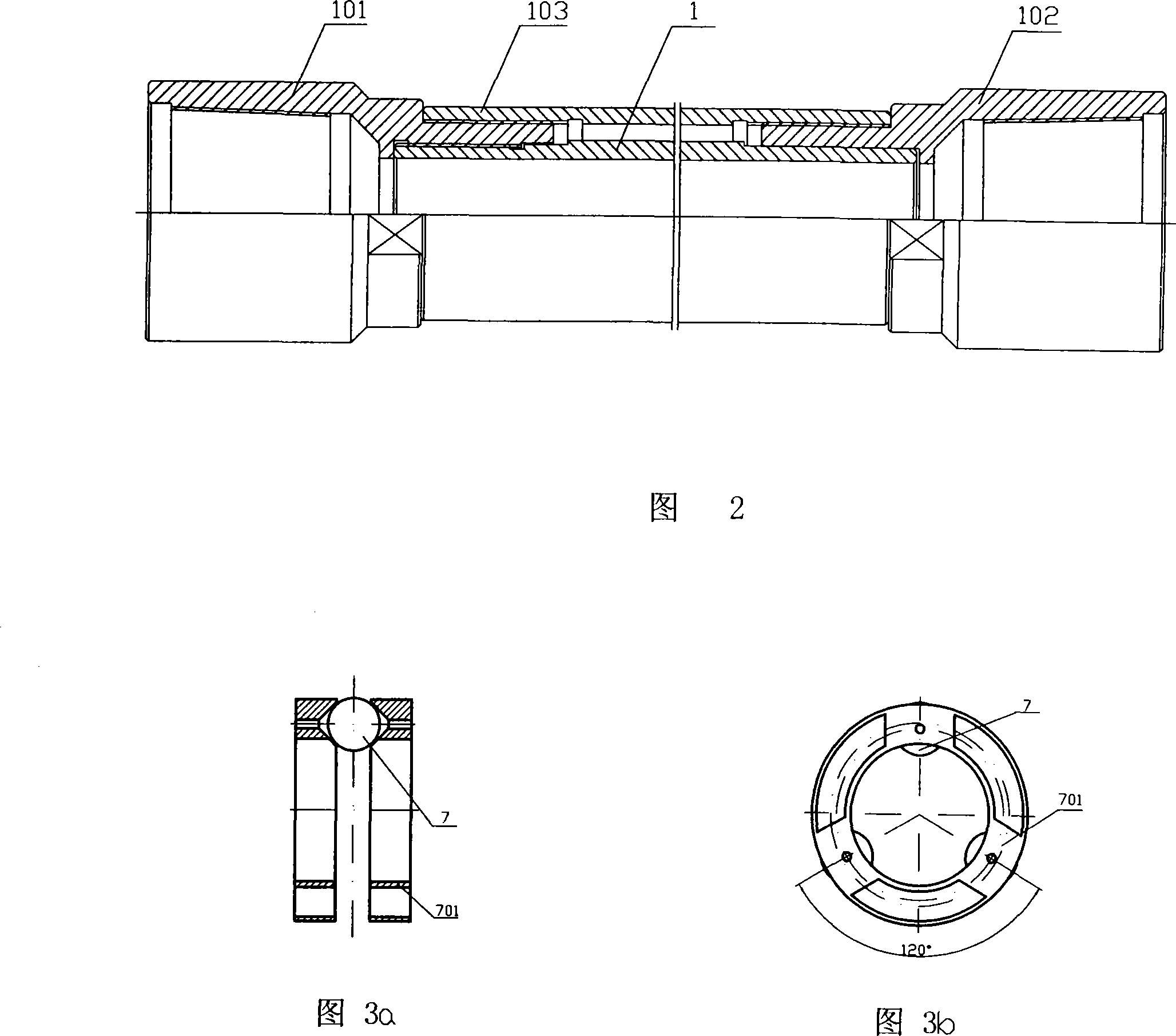
[0034] like figure 2 As shown, the two ends of the pump barrel 1 are provided with upper and lower couplings 101 and 102. The improvement of the present invention to the pump barrel unit is: a strengthening pipe 103 is sleeved on the periphery of the pump barrel, and the two ends of the strengthening pipe are respectively connected to the upper and lower pipes. The lower couplings 101 and 102 are screwed together, so that the pump barrel forms a double-tube structure, and the strength is greatly enhanced.

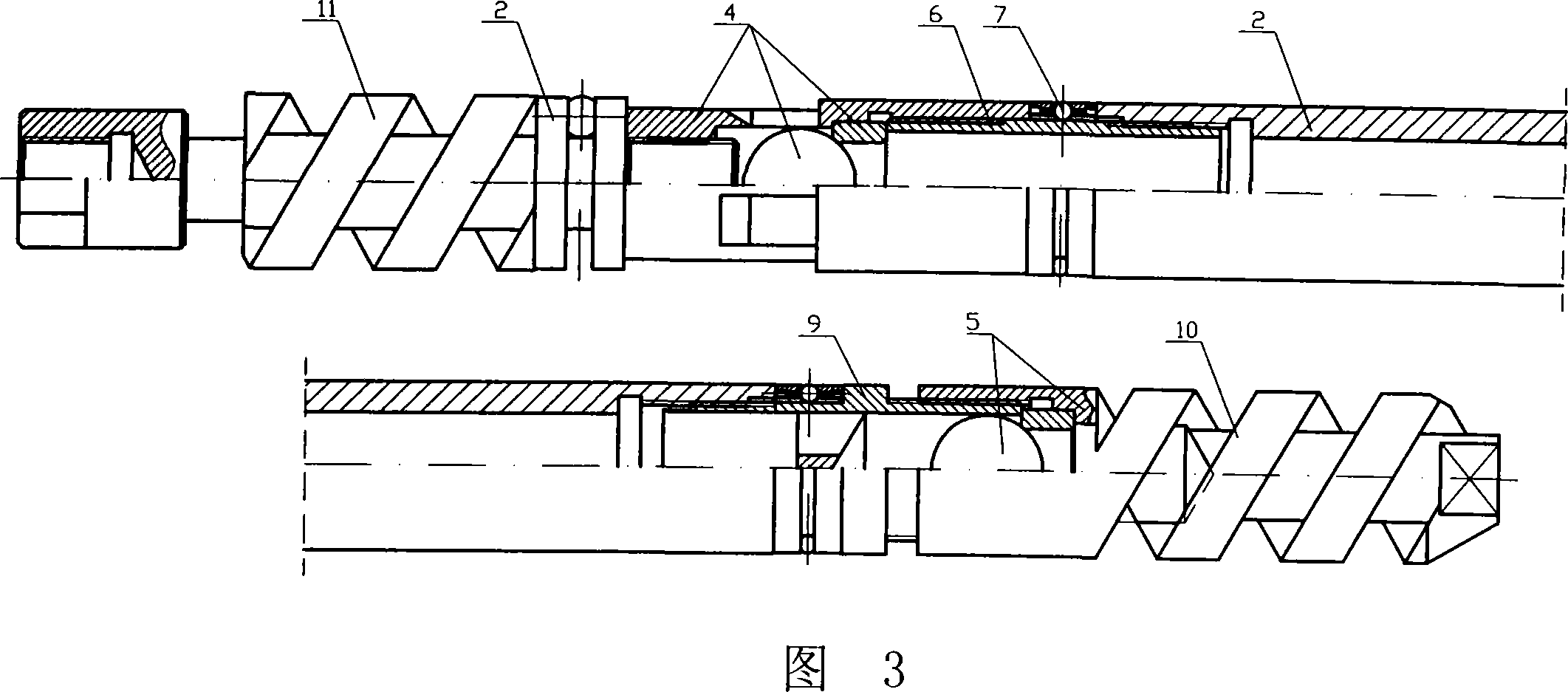
[0035] like image 3 As shown in the figure, the plunger unit 3 is the core transformation unit of the present invention. Similar to the prior art, the upper and lower joints 6 and 9 of the plunger are respectively connected to the inlet and outlet valves 4 and 5. The ends h...


PUM


Abstract

The present invention discloses a centering rotary plunger piston oil-well pump, which includes a pump barrel with a plunger piston and a wrap; two ends of the pump barrel are provided with a upper and lower coupling; the plunger piston is provided with a oil inlet and outlet valve, and the upper end and lower end is provided with a thruster respectively with upper end of the plunger piston connects with a rotary device; the upper and lower end of the plunger piston is provided with a centering bead respectively, and the location of the centering beads can construct the plunger piston to onlyallow the centering bead external diameter point contacts with pump barrel cavity interior diameter point inside the pump cavity. The present invention discloses a centering rotary plunger piston oil-well pump with high work efficiency, and prevents sand sticking, abrasion and eccentric wear.

Description

technical field [0001] The invention relates to a centering rotary plunger oil pump. Background technique [0002] At present, the main structure of the oil well pump used in various oil fields is generally composed of three parts: the pump barrel, the plunger and the fixed valve. The conventional pump barrel is directly composed of the pump barrel and the couplings at both ends, with a built-in plunger, and the two ends of the plunger are separated Upper and lower inlet and outlet valves and fixed valves. Although the structure is simple, there are many drawbacks: when working, the plunger is pulled up or down by the sucker rod. Because the friction force of the plunger on the pump barrel is relatively large, there is also the problem that the plunger hits the fixed valve, not only the plunger The directional wear of the plug on the pump barrel is relatively large, and the working efficiency is naturally low. It is also prone to sand sticking, rod fracture, etc., resulting...

Claims


Application Information

Patent Timeline
Patent Type & Authority Patents(China)
IPC IPC(8): F04B47/02F04B53/14
Inventor 姚尔强鲁广立
Owner 姚尔强
Why Eureka
Try Eureka