
Injection cylinder in injection apparatus for molding metal material

一种金属材料、注射装置的技术,应用在压注缸领域

Inactive Publication Date: 2009-07-01
NISSEI PLASTIC IND CO LTD
View PDF2 Cites 2 Cited by
  • Summary
  • Abstract
  • Description
  • Claims
  • Application Information

AI Technical Summary

Problems solved by technology

[0010] In order to solve the aforementioned problems that occur when the cylinder liner is connected to the inside of the cylinder block by a tight fit, the present invention has been achieved

Method used


Image

  • Injection cylinder in injection apparatus for molding metal material
  • Injection cylinder in injection apparatus for molding metal material
  • Injection cylinder in injection apparatus for molding metal material

Examples


Embodiment Construction

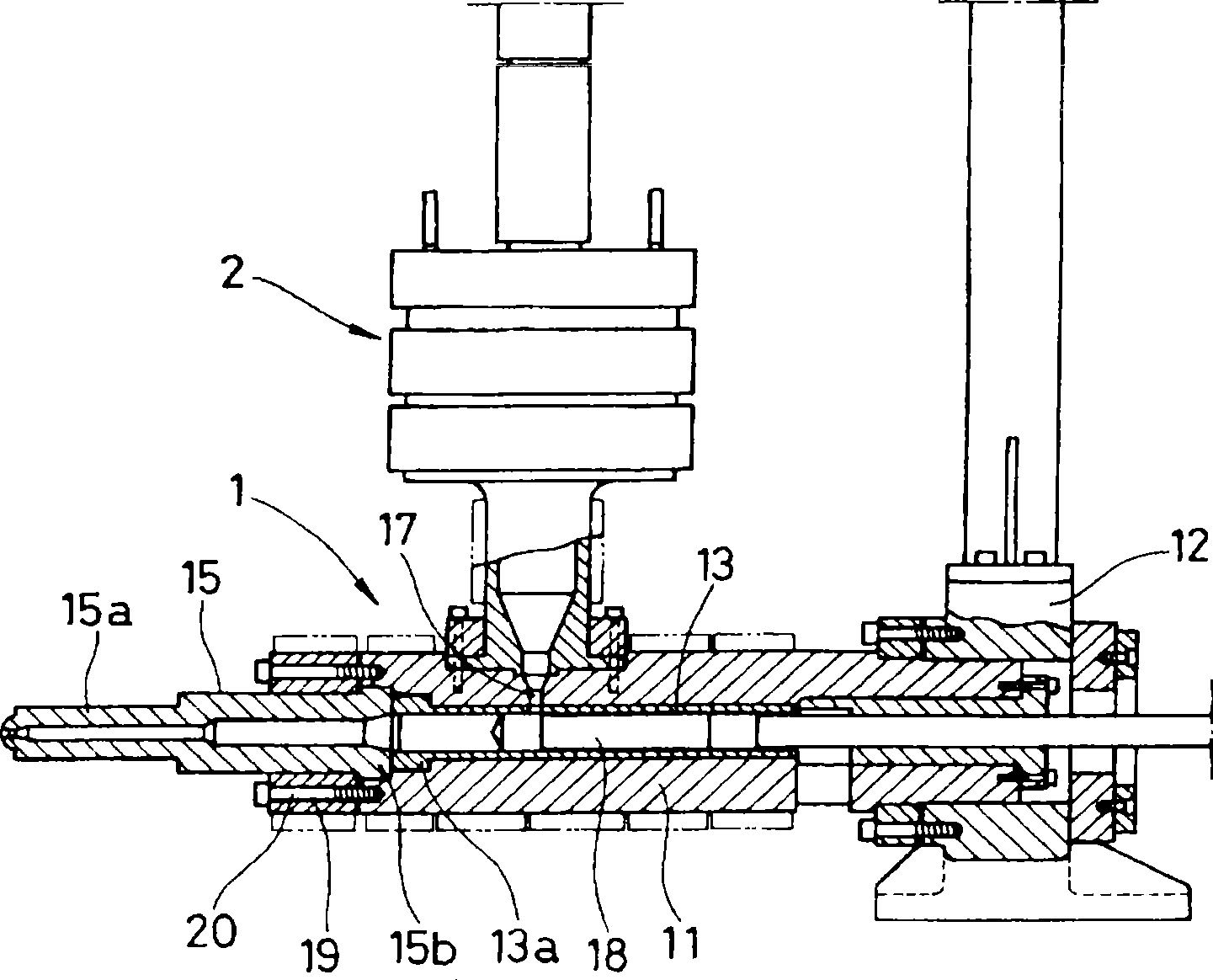
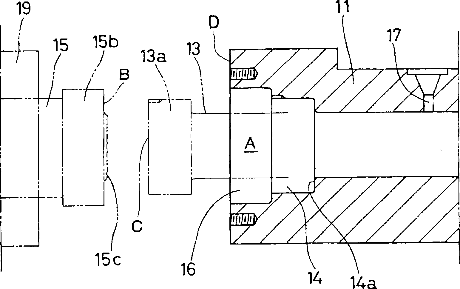
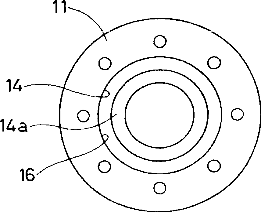
[0028] exist Figure 1-4 Among them, reference numeral 1 indicates an injection cylinder, which is placed horizontally on a base not shown, and the rear end of the cylinder body 11 passes through and is fixed on the holding plate 12 . The cylinder 11 has heating means on its circumference. Reference numeral 2 designates a material melting and storage unit, which is arranged at the front of the cylinder 11 .

[0029] The cylinder block 11 is composed of a cylinder having a first mounting portion 14 and a second mounting portion 16 at its front end opening A. As shown in FIG. The flange 13 a of the cylinder liner 13 is mounted to the first mounting portion 14 , and the flange 15 a of the nozzle member 15 is mounted to the second mounting portion 16 . A delivery opening 17 is formed on the front top side of the cylinder 11 . As mentioned, the cylinder liner 13 passes through the cylinder. The inner wall of the cylinder liner 13 forms a cylinder hole into which a plunger 18 is...


PUM


Abstract

An injection device of a molded metal material prevents a melt metal device from leaking between a cylinder and a spray nozzle piece when a cylinder liner is closely arranged in the cylinder. A pressure-injection cylinder of the injection device comprises the components as follows: a cylinder-shaped cylinder: the cylinder-shaped cylinder is provided with a first installing part in an opening in the front end, a second installing part with a larger diameter and an opening for delivery formed in the top area of the cylinder; a cylinder-shaped cylinder liner: the cylinder-shaped cylinder liner is provided with a flange in a circumference in the front end and a hole for delivery in the preset area of the top area, after plugged in the cylinder from the opening side the cylinder liner closely contacts an inner surface of the cylinder through heat expansion to install the flange in the first installing part, and the hole for delivery in the same position with the opening; a cylinder-shaped spray nozzle piece: the cylinder-shaped spray nozzle piece is provided with a spray nozzle in the end, a flange which is arranged in the second installing part in a circumference in the end, and a back surface of the flange contacts the front surface of the flange in the cylinder liner; a connection ring surrounding the cylinder of the spray nozzle piece: the back surface of the connection ring is connected with the front surface of the spray nozzle piece and is fastened in the surface in the front of the cylinder through a bolt, and the spray nozzle piece is fastened with the flange of the cylinder liner used on the cylinder and plugged between the two elements.

Description

technical field [0001] The present invention relates to an injection cylinder in an injection device for molding metal material, in which molten metal material is injected into a mold from a front nozzle by using a plunger. Background technique [0002] Existing injection devices for molding metallic materials are classified into a screw type and a plunger type. Both types have injection cylinders that are almost identical in basic construction, differing only in the way the metal material is melted and injected. [0003] Screw-type injection devices have a cylinder with a nozzle piece attached at its front end and a delivery opening formed at its rear top. The powdered metal material charged from the delivery opening is heated to a molten state, after which it is rotated by screws to reach the front of the cylinder. The molten material is measured (piled up) at the front of the cylinder by moving the screw back, and then injected into the mold from the front nozzle by adv...

Claims


Application Information

Patent Timeline
Patent Type & Authority Applications(China)
IPC IPC(8): B22D17/20B22D35/04
CPCB22D17/203B22D17/22B22D41/00B23P15/24B22D17/04
Inventor 甲田纪泰宫川守竹内康彦
Owner NISSEI PLASTIC IND CO LTD
Learn More