Ultrasonic equipment and image capturing method

An ultrasonic and equipment technology, applied in the field of ultrasonic equipment, can solve problems such as deflection or swing

Inactive Publication Date: 2009-07-01
SIEMENS CHINA
View PDF0 Cites 19 Cited by
  • Summary
  • Abstract
  • Description
  • Claims
  • Application Information

AI Technical Summary

Problems solved by technology

However, the needle knife has movement such as deflection or wobble when performing operations such as cutting, and some parts of the needle knife (such as the blade) may move out of the ultrasound image

Method used


Image

  • Ultrasonic equipment and image capturing method
  • Ultrasonic equipment and image capturing method
  • Ultrasonic equipment and image capturing method

Examples


Embodiment 1

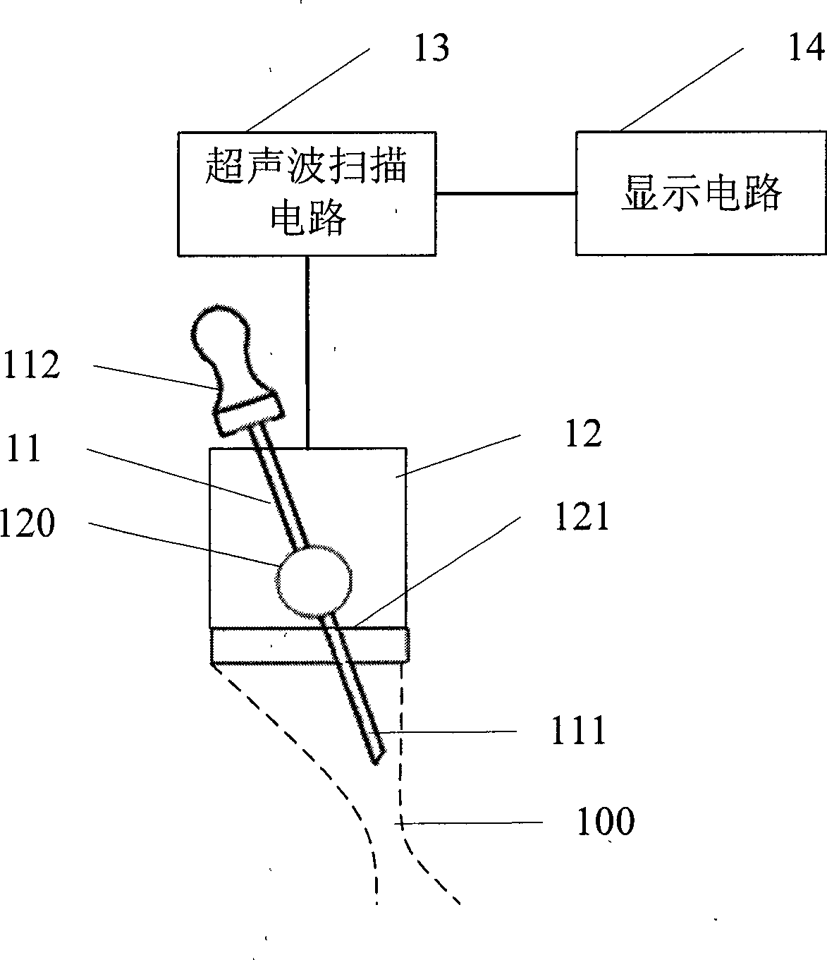
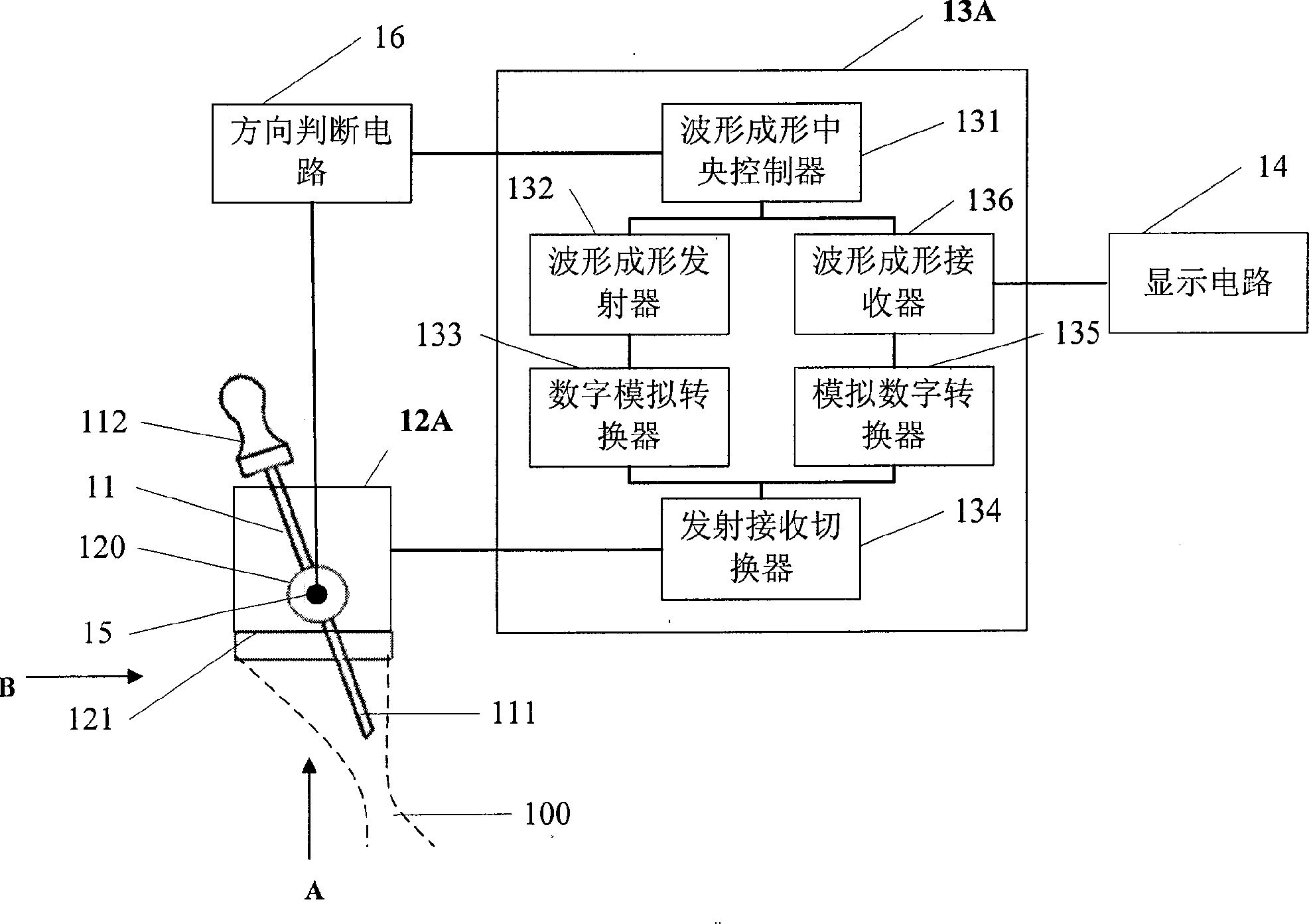
[0045] figure 2 It is a schematic diagram of the structure of the ultrasonic device in the first embodiment of the device of the present invention. Such as figure 2 As shown, the ultrasonic equipment in this embodiment includes figure 1 The needle blade 11, the ultrasonic probe 12A, the ultrasonic scanning circuit 13A, the angle measurement sensor 15, the direction judgment circuit 16, and the display circuit 14 are shown.

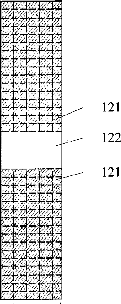
[0046] The ultrasonic probe 12A includes a sensor array 121 for transmitting an ultrasonic transmission signal from the ultrasonic scanning circuit 13A, and outputting the received ultrasonic feedback signal to the ultrasonic scanning circuit 13A.

[0047] The needle knife 11 is mounted on the ultrasonic probe 12A through a rotating shaft 120 connected between the blade portion 111 and the handle 112 and can swing around the rotating shaft 120. The axis of rotation 120 is parallel to the plane where the sensor array 121 is located, and the blade 111 of the...

Embodiment 2

[0070] Figure 6 It is a schematic structural diagram of the ultrasonic device in the second embodiment of the device of the present invention. Such as Figure 6 As shown, the ultrasonic equipment in this embodiment includes figure 1 The needle blade 11, the ultrasonic probe 12B, the ultrasonic scanning circuit 13B, the angle measurement sensor 15 and the driver 17, and the display circuit 14 are shown.

[0071] The needle knife 11 is mounted on the ultrasonic probe 12B through a rotating shaft 120 connected between the blade portion 111 and the handle 112 and can swing around the rotating shaft 120. The shaft 120 is parallel to the plane where the sensor array 121 is located, and the blade 111 of the needle knife 11 is within the coverage of the ultrasonic signal emitted by the sensor array 121, that is, the blade 111 of the needle knife 11 is in Figure 6 Shown is the energy band 100 generated by the ultrasonic signal. Such as Figure 6 As shown, the rotating shaft connecting ...


PUM


Abstract

The invention discloses an ultrasonic apparatus and an image capturing method. The image capturing of a needle-knife (11) and needle-knife visualization are realized by sending ultrasonic signals in the direction of the cutting part (111) of the needle-knife (11), converting the ultrasonic return signals into ultrasonic images and outputting the images through a display circuit (14). Further more, the ultrasonic apparatus make the irradiation direction of the ultrasonic beams lean to the motion direction of the cutting part (111) of the needle-knife (11) by measuring the derivation angle of the needle-knife (11) and adjusting the irradiation direction of the irradiated ultrasonic beams. According to the direction, the cutting part (111) of the needle-knife (11) is assured to be in the energy band generated by the ultrasonic wave all the time, thus, the cutting part of the needle-knife always presents in the ultrasonic images, and the needle-knife visualization stability is further improved.

Description

Technical field [0001] The invention relates to image acquisition technology, in particular to an ultrasonic device and an image capturing method with acupotomy as the target. Background technique [0002] Acupotomy is a traditional Chinese medicine method that can treat many complex diseases such as cervical spondylosis, arthritis, and femoral head necrosis. [0003] The needle knife is usually a steel needle with a handle, and the steel needle has a blade for cutting. The doctor can hold the handle of the needle knife to insert the steel needle into the patient's body, and use the blade to cut the diseased tissue inside the patient's body. [0004] However, the cutting process of the needle knife is carried out inside the patient's body, so the needle knife treatment process is a non-visual process. The doctor can only operate the needle knife based on his experience, so that the needle knife treatment has potential such as damage to normal tissues. Danger. [0005] At present,...

Claims


Application Information

Patent Timeline
Patent Type & Authority Applications(China)
IPC IPC(8): A61B8/13A61B17/32
Inventor 朱磊徐元景
Owner SIEMENS CHINA
Why Eureka
Try Eureka