
In-situ digitalization method and apparatus for transforming plant primary equipment

A technology of primary equipment and substation

Active Publication Date: 2009-06-24
北京天能继保电力科技有限公司
View PDF0 Cites 32 Cited by
  • Summary
  • Abstract
  • Description
  • Claims
  • Application Information

AI Technical Summary

Problems solved by technology

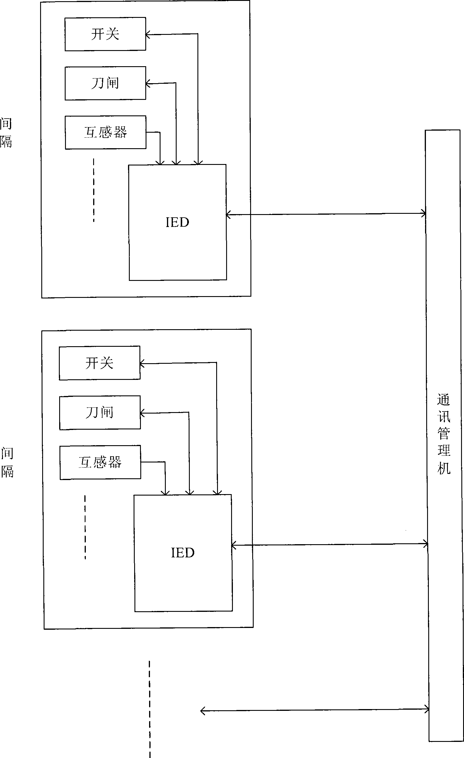
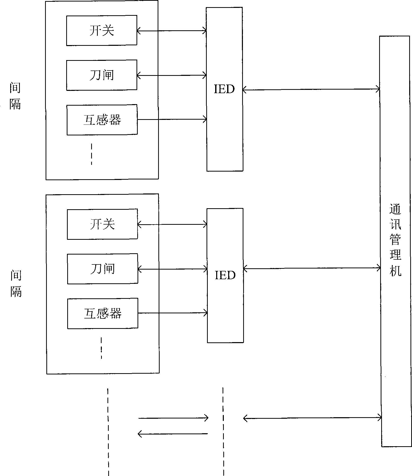
The biggest obstacle faced by the substation automation system adopting this mode is that the intelligent electronic device IED needs to collect the information of the basic components such as switches in each compartment of the equipment every time the intelligent electronic device IED needs the information of the primary equipment of the substation, and uses a large number of IEDs. Due to the limitations of the development background, operating experience and technical level of the IEDs of the manufacturer, or even different models of the same manufacturer, the communication protocols and user interfaces used are different, so it is difficult to achieve seamless integration and interoperability, and additional hardware ( Such as protocol converter) and software to achieve IED interconnection, and user training is required, which greatly weakens the advantages and significance of substation automation, and a considerable part of the system functions are set repeatedly, and information resources are not shared, resulting in The field wiring is complicated, and the communication protocols of the interfaces of various parts of the system are inconsistent, which increases investment and affects the reliability of the system, and affects the openness and scalability of the entire system

Method used


Image

  • In-situ digitalization method and apparatus for transforming plant primary equipment
  • In-situ digitalization method and apparatus for transforming plant primary equipment
  • In-situ digitalization method and apparatus for transforming plant primary equipment

Examples


Embodiment Construction

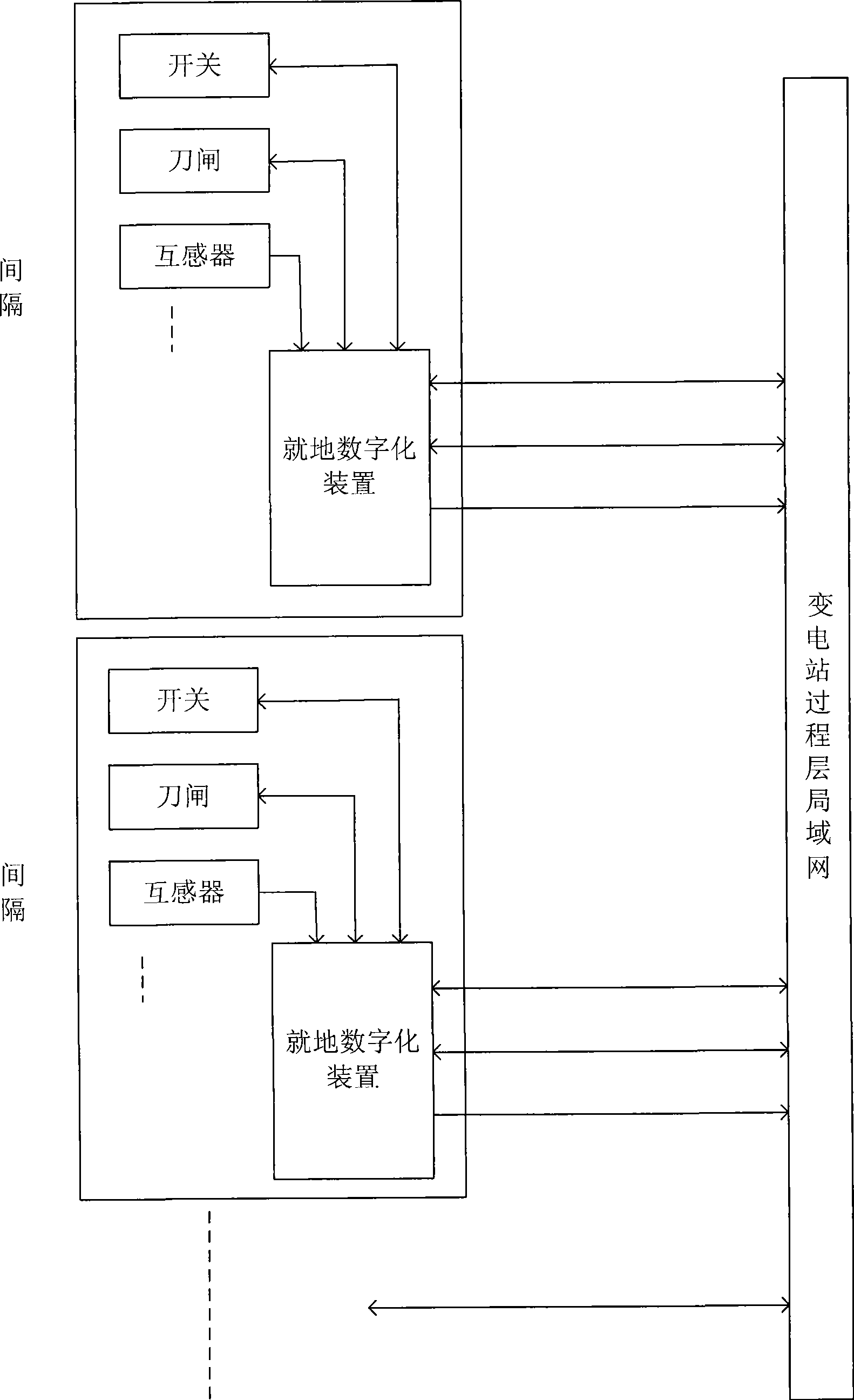
[0041] The present invention will be described below in conjunction with the accompanying drawings. image 3 It is a schematic diagram of the connection between the in-situ digitization device and other equipment of the present invention; Figure 4 It is a module block diagram of the in-situ digitization device of the present invention; Figure 5 It is a block diagram of the analog quantity access unit in the local digitization device of the present invention; Figure 8 It is a schematic diagram of in-situ digitization of each interval of the present invention.

[0042] Such as image 3 As shown, the in-situ digitization device of the present invention is arranged in each compartment, that is, as Figure 8 As shown, the incoming line interval, the high-voltage PT interval, the high-voltage bus coupling interval, the main transformer high-voltage main incoming interval, the main transformer low-voltage main incoming interval, the main transformer body interval, the utility p...


PUM


Abstract

The invention relates to an in-situ digitization method and a device of primary equipment of a substation; the in-situ digitalizer is arranged in each gap of the primary equipment on a spacing layer of the substation; the in-situ digitalizer respectively collects the status quantity such as a switch and a disconnecting link and the like in the same gap to convert into GOOSE format message, and respectively collects mutual inductor digital quantity and analog quantity information in the same gap to convert into sampling value transport format message, and the information processed by the in-situ digitization is sent out to a local area network in a process layer of the substation; the local area network in the process layer receives the GOOSE format message for converting into the open-closed operation control of the switch and the disconnecting link. The in-situ digitization method and the device thereof of the substation share the information in a uniform information platform, and the communication network is used for replacing control cables, thus being convenient for the design, construction, extension-construction of the substation, improving the reliability, further improving automation and management level and reducing comprehensive construction cost.

Description

technical field [0001] The invention relates to the field of electric power technology, in particular to a method and device for in-situ digitalization of primary equipment in substations. Background technique [0002] In recent years, the continuous adoption of new technologies such as computer chips and networks has fundamentally changed the basic appearance of traditional substations: fully digital equipment, systems composed of networks, supplemented by mature dispatching automation systems, are continuously improving the operation of substations. The degree of automation and reliability, and can gradually and truly apply the functions that automation should be able to achieve, that is, automation is no longer a beautiful and unusable flower shelf, but can really solve and meet the problems and needs that arise in the actual operation of production. Substation automation The system has basically been accepted and used by users. [0003] The substation automation system ...

Claims


Application Information

Patent Timeline
IPC IPC(8): H02J13/00
CPCY04S40/124Y02B90/2638Y02B90/20
Inventor 王海吉刘海波李春久
Owner 北京天能继保电力科技有限公司
Learn More