
Reduction reaction furnace for polysilicon

A reaction furnace and polysilicon technology, applied in the growth of polycrystalline materials, silicon, single crystal growth, etc., can solve the problems of lengthening the production of silicon rods, difficulty in expanding the production scale, time-consuming and labor-consuming, etc., to improve the yield and production efficiency , avoid shaking and breaking, and reduce production costs

Inactive Publication Date: 2009-06-24
袁建中
View PDF0 Cites 4 Cited by
  • Summary
  • Abstract
  • Description
  • Claims
  • Application Information

AI Technical Summary

Problems solved by technology

During the production process, it is necessary to open the furnace body (lift the furnace body with a crane), install and process the silicon rods, and then cover the furnace body after installation and processing (put it back with a crane). This process is time-consuming and labor-intensive.
If the production efficiency is improved, the production of silicon rods needs to be lengthened, and the silicon rods installed on the chassis must be placed vertically, otherwise the production of silicon rods is unstable and prone to breakage, so a higher factory building is required
It is more troublesome to open and put back the furnace body greater than 2 meters high. If the production scale is expanded, the factory building will be expanded higher. Therefore, it is difficult to expand the production scale with a reduction furnace of this structure; The furnace body must be opened when the silicon core is installed, which makes the production cycle longer and the production efficiency lower, which is not suitable for high-efficiency large-scale production

Method used


Image

  • Reduction reaction furnace for polysilicon
  • Reduction reaction furnace for polysilicon
  • Reduction reaction furnace for polysilicon

Examples


Embodiment Construction

[0017] The features of the polysilicon reduction reaction furnace of the present invention will be further described below in conjunction with the accompanying drawings and specific examples.

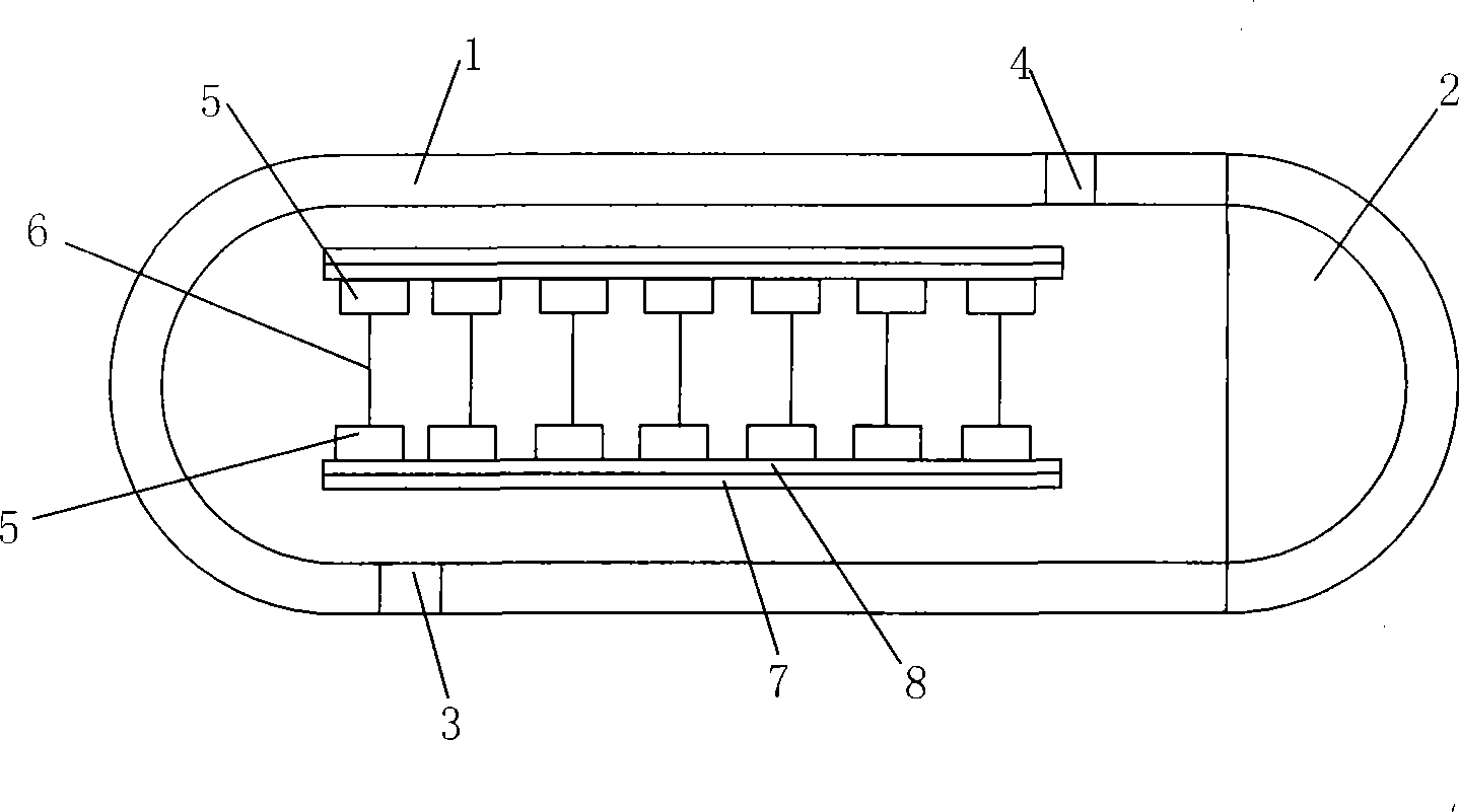
[0018] Such as figure 2 , 3 , 4, and 5, including furnace body 1, electrode 5 placed in furnace body 1 and silicon core 6 connected to the electrode, air inlet 3, exhaust port 4, movable furnace placed at the opening of furnace body 1 The door 2 and the movable or fixed electrode plate 7 separated from the furnace body 1, the central axis of the furnace body 1 is placed along the horizontal direction.

[0019] The electrode 5 is fixed at one end or at both ends on the electrode disc 7 , and there is an insulating layer 8 between the electrode 5 and the electrode disc 7 . In this embodiment, both ends of the electrode 5 are fixed on the electrode disk 7 .

[0020] The air inlet 3 and the air outlet 4 are placed on the furnace body 1 or the movable furnace door 2 . In this embodiment...


PUM


Abstract

The invention provides a polysilicon reduction reaction furnace, which comprises a furnace body, an electrode arranged in the furnace body and a silicon core connected with the electrode, an air inlet, an air outlet, an active furnace door arranged on the opening of the furnace body, and an electrode tray which is separated with the furnace body but moves or are fixed. The central axis of the furnace body is arranged along the horizontal direction. The reduction reaction furnace is used for producing polysilicon, which can easily expand the scale of production, shortens the production period, saves production cost, and increases the yield and productivity effect.

Description

technical field [0001] The invention relates to a silicon production device, in particular to a polysilicon reduction reaction furnace. Background technique [0002] At present, the production method of polysilicon generally uses quartz sand to be smelted and purified to 98% in an electric arc furnace to produce industrial silicon; then the industrial silicon is crushed and mixed with anhydrous HCl in a fluidized bed reactor at a temperature of about 300 °C. Medium reaction to generate easily soluble SiHCl 3 , while forming a gaseous mixture (H 2 , HCl, SiHCl 3 、SiCl 4 , Si). The above-mentioned gaseous mixture is then further purified and decomposed, and the purified SiHCl is purified 3 Using high-temperature reduction process, with high-purity SiHCl 3 in H 2 Reductive deposition in the atmosphere to generate polysilicon. [0003] The above-mentioned chemical vapor deposition process is carried out in a reduction furnace. Usually, the reduction furnace includes a fu...

Claims


Application Information

Patent Timeline
Patent Type & Authority Applications(China)
IPC IPC(8): C30B29/06C01B33/03C30B28/14
Inventor 袁建中
Owner 袁建中
Learn More