
Method for manufacturing metal hand tool

A manufacturing method and technology of hand tools, applied in the field of hand tools, can solve the problems of easy falling off, inconspicuous marking effect, short-term marking effect, etc., and achieve the effect of obvious marking effect

Inactive Publication Date: 2009-06-24
JIN XIANG KAI IND
View PDF0 Cites 7 Cited by
  • Summary
  • Abstract
  • Description
  • Claims
  • Application Information

AI Technical Summary

Problems solved by technology

At present, there are two commonly used graphic and text marking methods. One is that when the hand tool is cast or forged, a protruding or recessed graphic and text mark is directly formed on the surface, and then electroplated after forming, but after electroplating, the entire hand tool is uniform. It is the same color, which cannot highlight the part of the image and text, so that the effect of the logo is not obvious
[0003] Another marking method is to electroplate the hand tool after it is formed, and then print the logo text on the surface after the electroplating is completed. The logo is printed in color to highlight the logo effect. However, the printed text is not easy and smooth. The surface of the electroplating layer is combined, and the printed graphics and texts are easily peeled off due to friction during operation, so the marking effect is extremely short-lived
[0004] Therefore, the existing method of directly forming graphics and texts and then electroplating has no obvious marking effect, while the method of color printing graphics and texts on the surface of hand tools has a better marking effect, but it has the defect that it is easy to fall off. Both of them have been further improved. the necessity of

Method used


Image

  • Method for manufacturing metal hand tool
  • Method for manufacturing metal hand tool
  • Method for manufacturing metal hand tool

Examples


Embodiment Construction

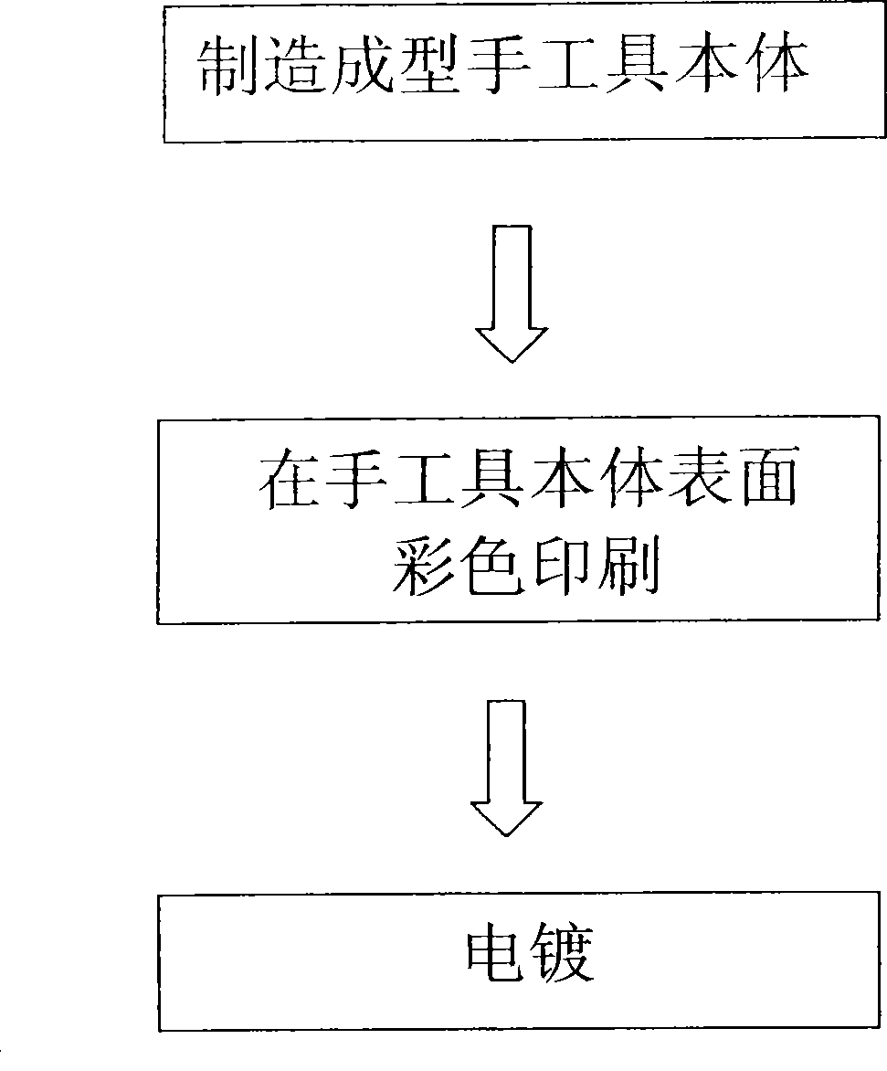
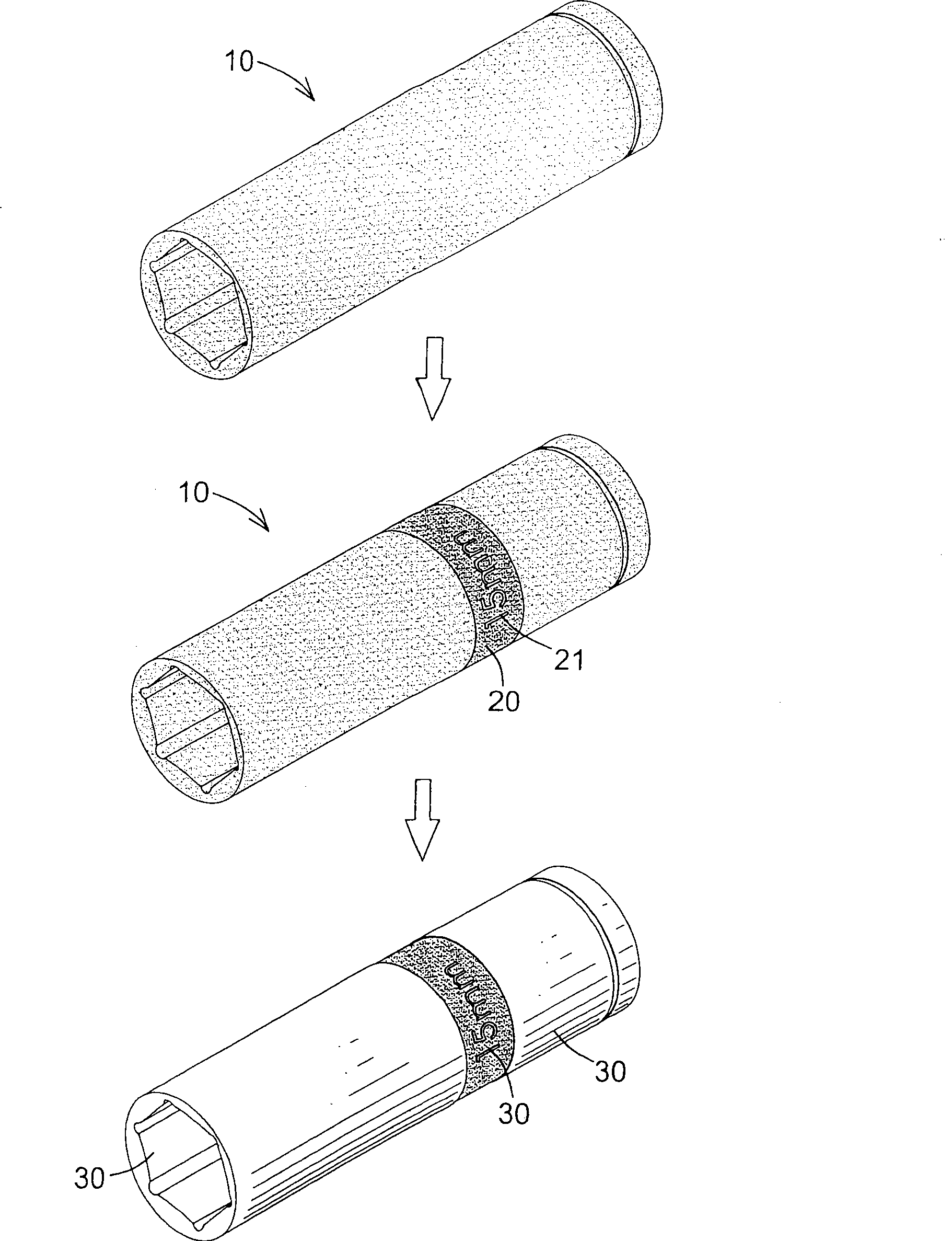
[0021] see figure 1 and figure 2 shown, where figure 2 The sleeve is taken as an example to illustrate its manufacturing method, but it is not limited to manufacturing the sleeve, it can also be applied to other metal hand tools such as wrenches or screwdrivers, so it is hereby explained first.

[0022] Manufacturing method of the present invention comprises:

[0023] 1. Manufacturing the shaped hand tool body: forming the hand tool body 10 by casting or forging;

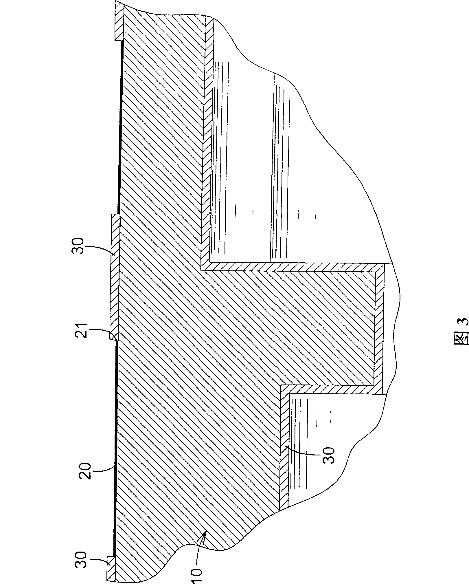
[0024] 2. Color printing: color printing is performed on a predetermined area on the surface of the hand tool body 10 to form a printing layer 20, which can be printed in one color or multi-colored in printing. The hollowed-out graphic part 21 is formed within the range of the printing layer 20;

[0025] 3. Electroplating: electroplating on the surface of the hand tool body 10, because the pigment of the printing layer 20 is an insulator, so during electroplating, the electroplating layer 30 will not adhere to...


PUM


Abstract

A manufacturing method for metal hand tools comprises the following manufacturing steps: 1. A molding hand tool body is manufactured; 2. Color printing: color printing is carried out on a preset region of the surface of the tool body so as to form a printing layer; part of region in the range of the printing layer is designed to be fretwork shape; the position of the fretwork is a picture and text shape to be presented; 3. Plating: the surface of the hand tool body is plated; namely, a plating layer is formed on the surface of the hand tool body outside the printing layer and the surface of the position of the fretwork. The surface of the hand tool body manufactured according to the steps is provided with the printing layer. A fretwork picture and text part forming the picture and text shape is arranged in the range of the printing layer; and the surface of the fretwork picture and text part and the surface of the rest position of the hand tool body are provided with the plating layer; as the plating layer forming up the picture and text shape is arranged in the range of the color printing, the picture and text shape can be made to prominent; and as the hand tool body is molded, and then is printed on the surface, the paint can firmly attach on the rough surface of the metal and is difficult to drop off.

Description

technical field [0001] The invention belongs to the technical field of hand tools, in particular to a metal hand tool marked with pictures and texts on the surface. Background technique [0002] Hand tools such as sockets, fixed wrenches, adjustable wrenches, ratchet wrenches, screwdrivers... and other hand tools are tools that are often used in daily life. In order to highlight the product's trademark and product specifications, manufacturers will make graphics on metal hand tools logo. At present, there are two commonly used graphic and text marking methods. One is that when the hand tool is cast or forged, a protruding or recessed graphic and text mark is directly formed on the surface, and then electroplated after forming, but after electroplating, the entire hand tool is uniform. It is the same color, which cannot highlight the part of the graphic and text, so that the effect of the logo is not obvious. [0003] Another marking method is to electroplate the hand tool ...

Claims


Application Information

Patent Timeline
IPC IPC(8): C25D5/02
Inventor 洪秋月
Owner JIN XIANG KAI IND
Learn More