
Rolling triangular robot

A robot and triangular technology, applied in the field of rolling robots, can solve problems such as the inability to see two-stage or multi-stage transmission electric push rods, small expansion ratio of electric push rods, and high requirements for working environments, achieving simple structure, easy to understand, Effects that are easy to manufacture and engineer

Inactive Publication Date: 2009-06-24
BEIJING JIAOTONG UNIV
View PDF0 Cites 14 Cited by
  • Summary
  • Abstract
  • Description
  • Claims
  • Application Information

AI Technical Summary

Problems solved by technology

[0006] In the current market, the expansion ratio of the electric push rod is very small, and the range is basically within 2:1. It is not possible to see the electric push rod that realizes two-stage or multi-stage transmission. The existing two-stage or multi-stage push rods are pneumatic or hydraulic. Drive push rod, but its working environment requires high requirements, and it needs the support of cylinder and hydraulic cylinder, which also puts forward requirements for space

Method used


Image

  • Rolling triangular robot
  • Rolling triangular robot
  • Rolling triangular robot

Examples


Embodiment Construction

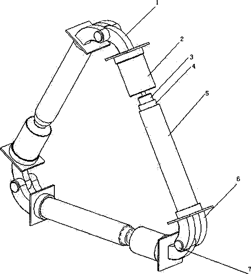
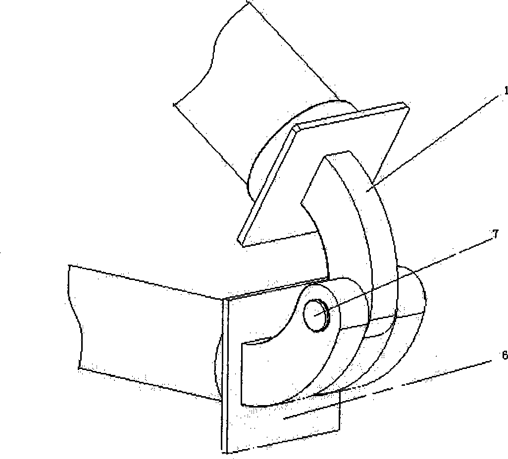
[0029] Rolling one side of a triangle robot, see image 3 , including motor 2, one-section screw 3, two-section screw 4 with one section of internal thread, three-section sleeve 5 with one section of internal thread, sleeve joint 6 and motor joint 1;

[0030] The tail of the motor 2 is fixed on the motor connector 1, and the output shaft of the motor 2 is fixed to the right end of a screw 3 with a tight nail;

[0031] One section of screw rod 3 is threadedly connected with two sections of screw rod 4;

[0032] Two-section screw 4 threads are connected with three-section sleeve 5 threads;

[0033] The three-section sleeve 5 is fixed on the sleeve joint 6;

[0034] Motor joint 1, motor 2, one-section screw rod 3, two-section screw rod 4, three-section sleeve 5 and sleeve joint 6 form one side of a rolling triangle robot;

[0035] The three sides of the rolling triangle robot have the same structure and size, and the motor joint 1 of each side is connected with the sleeve join...


PUM


Abstract

The invention discloses a rolling triangular robot, and relates to a rolling robot. One side of the robot comprises an electric motor (2), a section of a screw rod (3), two sections of screw rods (4), three sections of sleeves (5), a sleeve joint (6) and an electric motor joint (1), wherein the tail part of the electric motor is fixed on the electric motor joint; an output shaft of the electric motor is fixed with the right end of one section of the screw rod through a fastening nail; a section of the screw rod is in threaded connection with two sections of the screw rods; two sections of the screw rods are connected with three sections of the screw rods through the threads; three sections of the screw rods are fixed on the sleeve joint; and the electric motor joint, the electric motor, the one section of the screw rod, the two sections of the screw rods, the three sections of the screw rods and the sleeve joint form one side of the rolling triangular robot. The structures and the sizes of three sides of the rolling triangular robot are the same, and the electric motor joints of each side are connected with the sleeve joint and a cylinder pin of another side in turn through a cylinder pair so as to form the rolling triangular robot. The rolling triangular robot has the advantages of simple structure and easy realization, and provides acknowledge help for middle and primary students on geometric solids and moving robots.

Description

technical field [0001] The invention relates to a rolling robot, which realizes the linear motion of a triangular structure robot. Background technique: [0002] In the research field of rolling robots, rolling spherical robots are a large family. In 1996, Aarne Halme, Jussi Suomela, TorstenSchonberg and YanWang of Helsinki University of Technology designed the first spherical robot. They set up a driving wheel, and a motor drives the driving wheel to roll in the spherical shell. By changing the center of gravity of the system, Realizing the rolling of the sphere, as the first spherical robot design in history, it has an important reference and enlightenment for the continued research of future scholars. [0003] Then there are rolling robots with many rotary structures such as rolling cylinder robots. [0004] However, this type of rotary robot has an obvious shortcoming that it has strict requirements on the terrain, and it will be difficult to realize normal operation u...

Claims


Application Information

Patent Timeline
Patent Type & Authority Applications(China)
IPC IPC(8): B62D57/02
Inventor 孔德隆刘伟徐文胜姚燕安
Owner BEIJING JIAOTONG UNIV
Learn More