
Semiconductor device and producing method thereof

A manufacturing method and semiconductor technology, applied in the fields of semiconductor devices, semiconductor/solid-state device manufacturing, electric solid-state devices, etc., can solve problems such as high conductivity and semiconductor substrate loss, and achieve the effect of reducing loss and increasing process costs.

Active Publication Date: 2009-06-17
SEMICON MFG INT (SHANGHAI) CORP
View PDF1 Cites 2 Cited by
  • Summary
  • Abstract
  • Description
  • Claims
  • Application Information

AI Technical Summary

Problems solved by technology

At the same time, the conductivity of the p-type doped well in the p-type semiconductor substrate 11 is relatively high, and the eddy currents generated in the semiconductor substrate flow along the semiconductor substrate, resulting in loss of the semiconductor substrate.

Method used


Image

  • Semiconductor device and producing method thereof
  • Semiconductor device and producing method thereof
  • Semiconductor device and producing method thereof

Examples


no. 1 example

[0069] The present invention has also tested some parameters of the formed planar spiral inductor, respectively provides the planar spiral inductor formed on the p-type doped well position, that is, the prior art, and the n-type on the p-type semiconductor substrate of the present invention. The doped well position and the planar spiral inductor formed on the p-type doped well and the deep n-type doped well are used for comparison. First, referring to Table 1 below, the sheet resistance and junction capacitance under different conditions are given, wherein the p-type doped well corresponds to the prior art, the n-type doped well corresponds to the first embodiment of the present invention, and the p-type doped well / deep The n-type doped well corresponds to the second embodiment.

[0070] Table 1

[0071] doped well p-type doped well n-type doped well P-type doped well / deep n-type doped well Sheet resistance

(ohm / sq) 1185

1120

1185

1250

...


PUM


Abstract

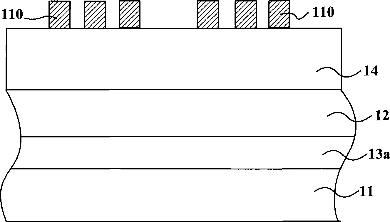
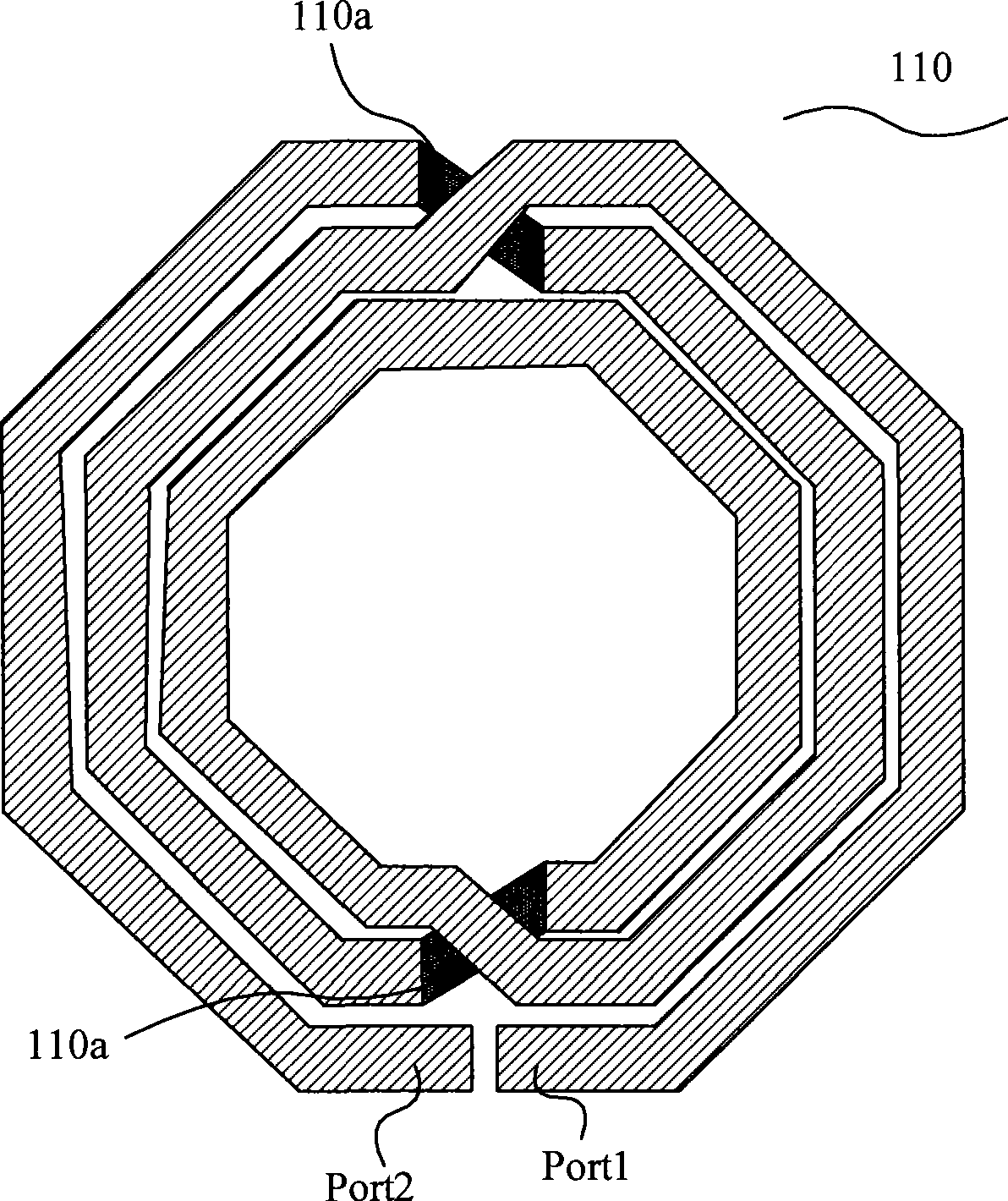
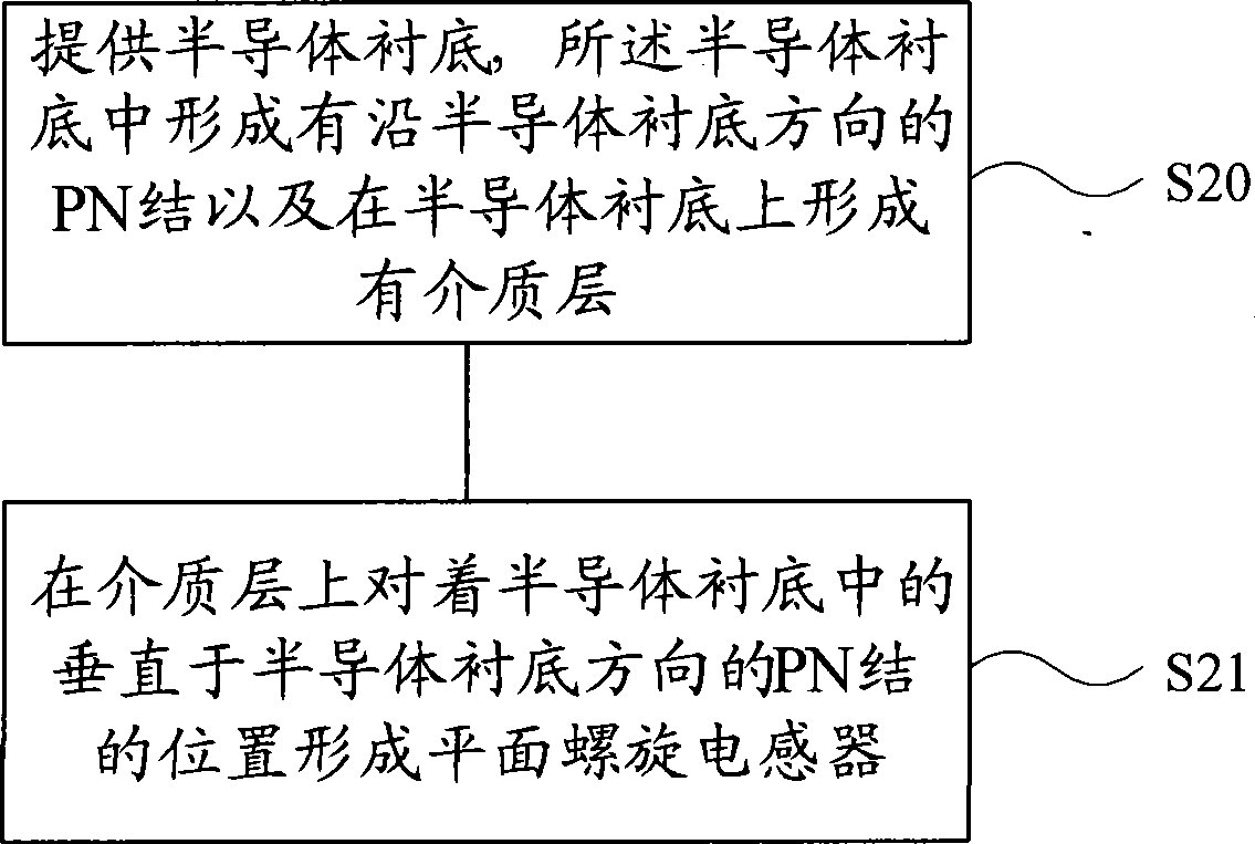
A manufacturing method for semiconductor devices comprises steps of providing a semiconductor substrate, wherein a PN junction is formed in the semiconductor substrate along the direction of the semiconductor substrate and a dielectric layer is formed on the semiconductor substrate, and forming a planar spiral inductor facing the position of the PN junction which is in the semiconductor substrate and is perpendicular to the direction of the semiconductor substrate on the dielectric layer. The invention further provides a semiconductor device. The planar spiral inductor facing the position of the PN junction which is in the semiconductor substrate and is perpendicular to the direction of the semiconductor substrate is formed on the dielectric layer, thereby reducing the loss of the planar spiral inductor in the semiconductor substrate.

Description

technical field [0001] The invention relates to the field of semiconductor devices and their manufacture. Background technique [0002] In the development of CMOS radio frequency integrated circuits (RFIC), the most urgent and difficult thing is to develop high-performance new devices and new unit circuits, which are the basis for realizing monolithic CMOS integrated RF front-end. As a key component in radio frequency integrated circuits, planar spiral inductors are the most difficult components to design and master in circuits, and their performance parameters directly affect the performance of radio frequency integrated circuits. On-chip inductors can realize the integration of inductors in radio frequency integrated circuits. [0003] Most of the on-chip planar spiral inductors are wound on silicon substrates by metal films. Compared with traditional wire-wound inductors, on-chip planar spiral inductors have the advantages of low cost, easy integration, low noise and low...

Claims


Application Information

Patent Timeline
Patent Type & Authority Applications(China)
IPC IPC(8): H01L27/06H01L21/822H01L21/02
Inventor 程仁豪
Owner SEMICON MFG INT (SHANGHAI) CORP
Learn More