Train speeding machine

A technology for trains and locomotives, applied in the field of train speed-increasing devices, can solve the problems of high cost of new materials, high energy consumption, etc., and achieve the effects of convenient operation, fast acceleration and fast braking

Inactive Publication Date: 2009-06-17
王玉强
View PDF0 Cites 9 Cited by
  • Summary
  • Abstract
  • Description
  • Claims
  • Application Information

AI Technical Summary

Problems solved by technology

Its disadvantages are: once the power is increased, more energy will be consumed; second, the cost of new materials is generally higher; third, no matter how the appearance is changed, there is always air resistance

Method used


Image

  • Train speeding machine

Examples


Embodiment Construction

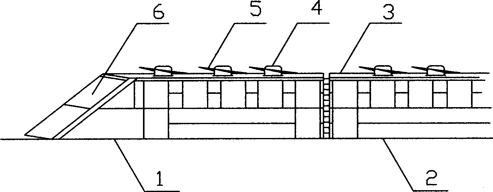
[0009] In the figure, a train speed-increasing device, which includes a locomotive 1 and a car body 2, is characterized in that: a number of brackets 4 are provided on the top 3 of the locomotive 1 and the car body 2, and the brackets 4 are provided with flying parts that can rotate back and forth. Wing 5 is provided with controller 6 in the headstock. The angle of flying wing 5 is elevation angle when advancing, and the resistance of air is changed into lifting force. Reduce the weight of the train to achieve the purpose of increasing the speed of the train. When braking, change the angle of its flying wing 5 into a depression angle, increase the air resistance, and convert the air resistance into braking force, which can effectively reduce the wear of the brake pads and shorten the braking time. distance.


PUM


Abstract

The invention relates to a train acceleration device. The train acceleration device comprises a train engine and a carriage body. The train acceleration device is characterized in that the top parts of the train engine and the carriage body are provided with a plurality of brackets; the brackets are provided with flying wings capable of rotating back and forth; and the inside of the train engine is provided with a controller. In marching, the angle of the flying winds is an elevation angle; and the air resistance is converted into lifting force. The weight of the train is lightened to achieve the aim of improving the speed of the train; in braking, the angle of the flying wings is changed to a depression angle; and the air resistance is increased and is converted into the braking force, thereby effectively reducing abrasion of a braking sheet and shortening the braking distance. The train acceleration device has the advantages of rapid acceleration, rapid braking, simple structure, convenient operation, energy conservation and environmental protection.

Description

technical field [0001] The invention relates to a vehicle, in particular to a train speed increasing device. Background technique [0002] At present, it is known that speeding up trains is the general trend, and there are three commonly used methods of speeding up: one is to increase power; the other is to replace lighter new materials; the third is to change the appearance to reduce air resistance. Its shortcoming is: one increases power and will consume more energy; Second, the cost of new materials is generally higher; Third, no matter how the appearance is changed, there is always air resistance. Invention content: [0003] The technical problem to be solved by the present invention is to overcome the deficiencies of the above-mentioned prior art, and provide a train speed increasing device which is simple in structure, easy to produce, and capable of changing air resistance to force. [0004] The technical solution adopted by the present invention to solve the above...

Claims


Application Information

Patent Timeline
Patent Type & Authority Applications(China)
IPC IPC(8): B61D17/02B61H11/00
CPCY02T30/32Y02T30/00
Inventor 宫锡和王玉强
Owner 王玉强
Why Eureka
Try Eureka