Speed regulating system for switch reluctance motor
A reluctance motor and switched reluctance technology, applied in the direction of single motor speed/torque control, AC motor control, control system, etc., can solve the problem of increasing the insulation level of motor windings
Inactive Publication Date: 2010-12-01
NIDEC BEIJING DRIVE TECH CO LTD
View PDF0 Cites 0 Cited by
- Summary
- Abstract
- Description
- Claims
- Application Information
AI Technical Summary
Problems solved by technology
But at this time, the voltage on the motor winding is also increased by K times, and the insulation level of the motor winding needs to be increased
Method used
View moreImage
Smart ImageViewing Examples

Examples
Embodiment Construction
Login to View More PUM
 Abstract
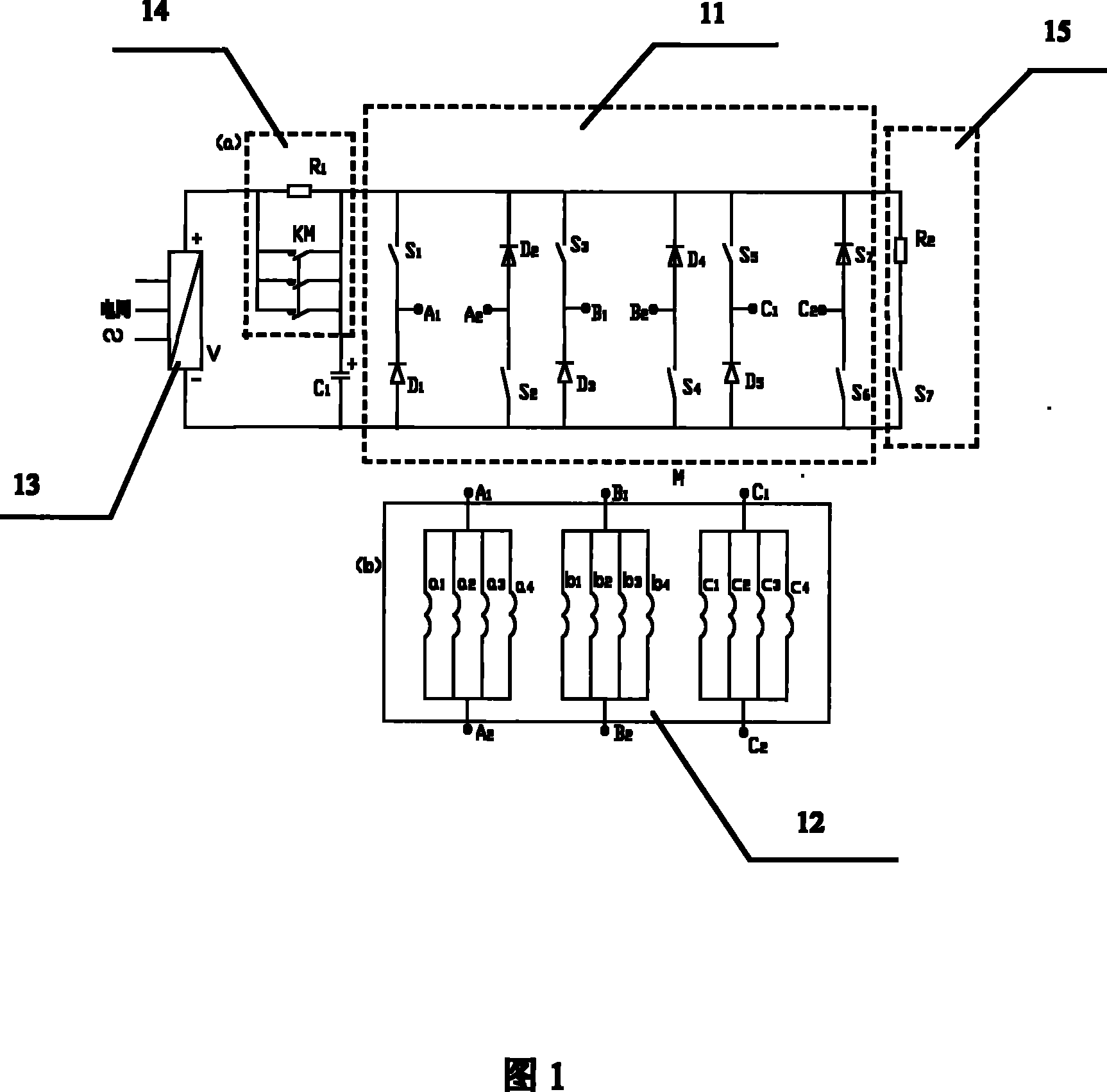
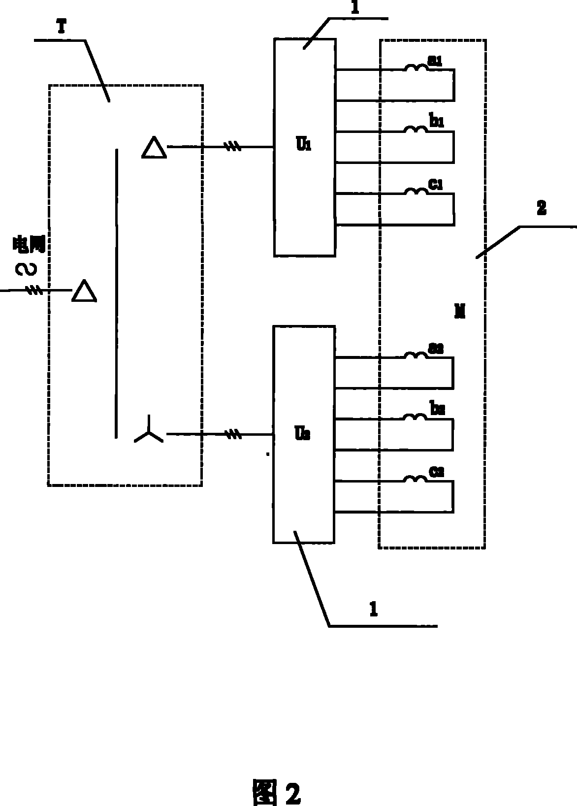
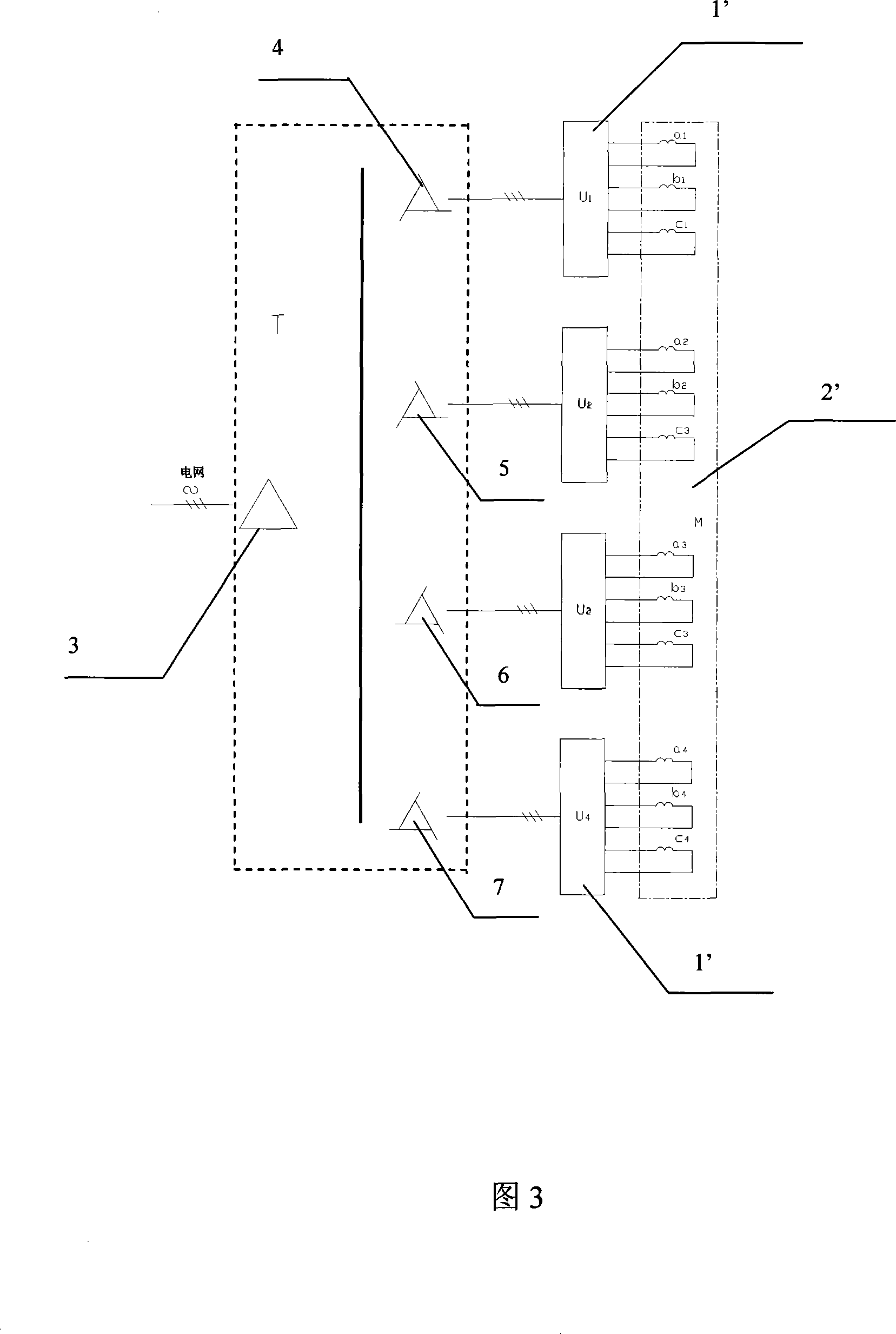
The invention aims to provide a speed regulating system of a switch reluctance motor, which is characterized by comprising a N-phase switch reluctance motor, K power units and a three-phase phase-shifting transformer, wherein the phase winding of the N- phase switch reluctance motor is divided into K groups; the K power units provide chopped current for phase windings of the N-phase switch reluctance motor divided into K groups; and the three-phase phase-shifting transformer provides three-phase power frequency power supplies for the K power units. The K power units are adopted to supply power to the N- phase switch reluctance motor by which the phase winding is divided into K groups, so the speed regulating system increases the power by K times, does not need to improve the voltage grade, and has improvements in the aspects of reducing the electromagnetic interference and noise. In addition, the three-phase phase-shifting transformer is adopted so that the waveform of supply current on the network side becomes good.
Description
A Switched Reluctance Motor Speed Control System technical field The invention relates to a new speed regulating device of a switched reluctance motor, in particular to the connection method of the stator coil in the switched reluctance motor and the driving mode of the motor winding. Background technique The switched reluctance motor speed control system consists of four parts: motor, power circuit, angular displacement sensor and control circuit. Due to its excellent performance, it has been more and more widely used in various fields. There are many structural types of switched reluctance motors, the number of phases is generally N, and the stator windings of each phase are connected by Z coils (Z is an even number), which can be connected in series, parallel or mixed. The coils are embedded on the poles of the stator, and the product NZ is the total number of coils and also the number of poles of the stator. The number of poles of the motor rotor is less than that ...
Claims
Login to View More Application Information
Patent Timeline
 Patent Type & Authority Patents(China)
IPC IPC(8): H02P6/08H02P6/14H02P25/092H02P25/098
Inventor 高超裘锦灼
Owner NIDEC BEIJING DRIVE TECH CO LTD
Features
- R&D
- Intellectual Property
- Life Sciences
- Materials
- Tech Scout
- Unparalleled Data Quality
- Higher Quality Content
- 60% Fewer Hallucinations
Learn More Browse by: Latest US Patents, China's latest patents, Technical Efficacy Thesaurus, Application Domain, Technology Topic, Popular Technical Reports.
© 2025 PatSnap. All rights reserved.Legal|Privacy policy|Modern Slavery Act Transparency Statement|Sitemap|About US| Contact US: help@patsnap.com