Suspension of a turbojet to an aircraft

A technology of suspension device and turbojet, which is applied in the direction of power plant, power plant arrangement/installation, aircraft parts, etc., can solve the problems of reduced fuel efficiency, performance decline, engine service life decline, etc., to improve fuel efficiency, Reduce the effect of distortion

Active Publication Date: 2009-06-10
SN DETUDE & DE CONSTR DE MOTEURS DAVIATION S N E C M A
View PDF1 Cites 12 Cited by
  • Summary
  • Abstract
  • Description
  • Claims
  • Application Information

AI Technical Summary

Problems solved by technology

The torque created by these two forces causes the engine to deflect along its axis, which changes the clearance between the stationary and rotating parts, resulting in reduced performance and reduced fuel efficiency
Another result is that friction between components leads to wear, which reduces the service life of the engine

Method used


Image

  • Suspension of a turbojet to an aircraft
  • Suspension of a turbojet to an aircraft
  • Suspension of a turbojet to an aircraft

Examples


Embodiment Construction

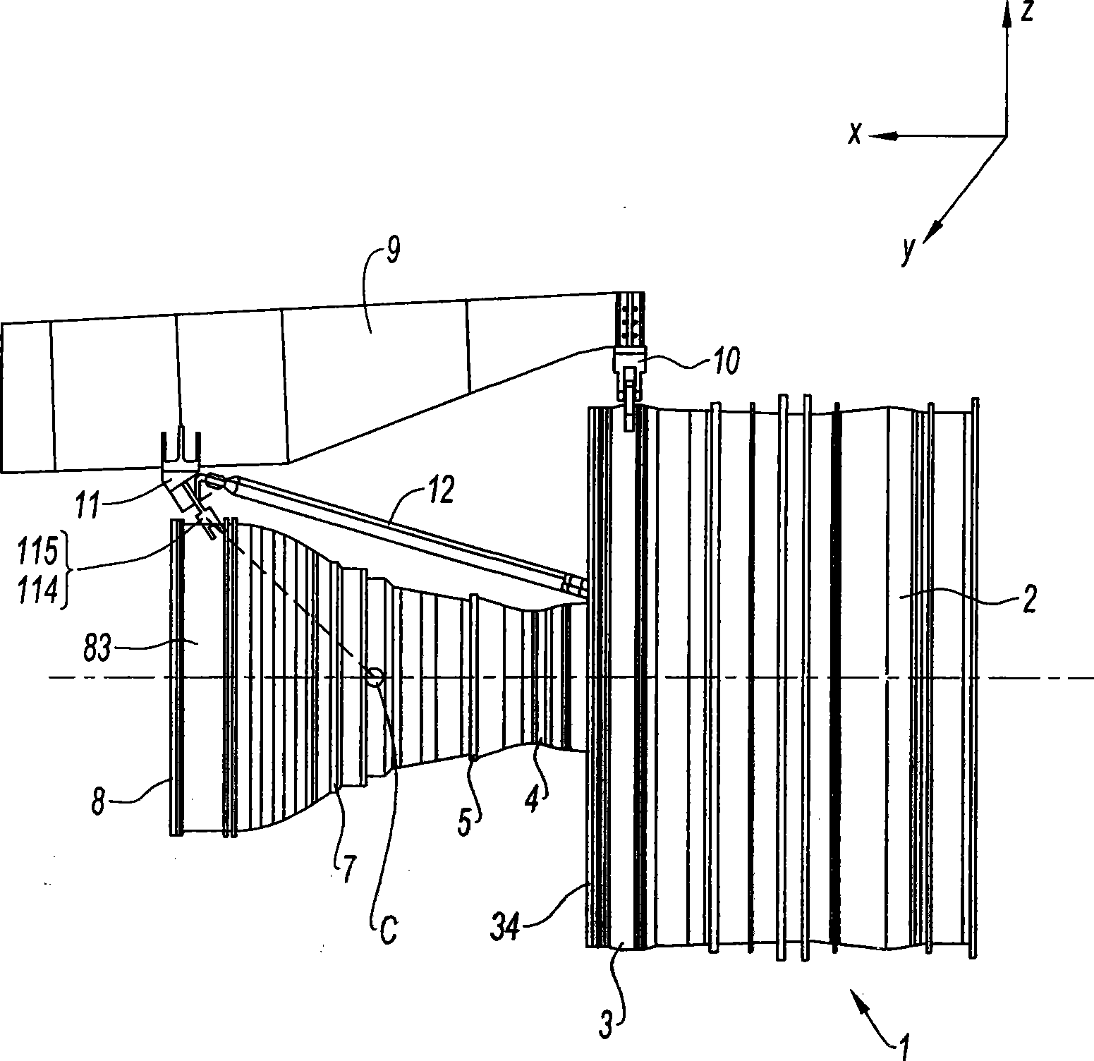
[0035] Such as figure 1 Shown, turbojet engine 1 is a turbofan type engine, and its fan case is shown in figure 2. The downstream of the fan casing 2 is the middle casing 3, and only the casing 34 can be seen in the figure. The upstream end of the air inlet is located at figure 1 Right side of drawing shown.

[0036] In the downstream position, the casing 4 of the compression section can be seen. The compression section communicates with the annular combustion chamber 5 . The turbine stage 7 is located downstream of the combustion chamber. At the extremity of the engine, there is an exhaust casing 8, which is a rear bearing support structure of known type. The coordinate system to which the axes and components of the individual forces and moments are directed includes an axis Ox parallel to the engine axis XX, which is assumed to be horizontal and extends from the upstream to the downstream end; the axis Oz is the vertical axis and the axis Oy is the transverse axis .

...


PUM


Abstract

The present invention relates to a balance suspension device for mounting a turbine engine on a suspension frame of a plane, the turbine engine comprises a front fan (2), an intermediate case (3) at low stream of the fan, the intermediate case has an external housing and a hub (35) connected together by a radial rod (360, and an exhaust case (8) with a housing (83) on a same axis XX, the suspension device comprises a front connection device (10) on the intermediate case (3), a rear connection device (11), which has at least two link rods (114, 115) connected to the external housing of the exhaust case (8), and a pair of thrust rods (12, 12') fixed on the hub (35) of the intermediate case (3) at their low stream end. The suspension device is characterized in that a plane formed by the two link rods (114, 115) of the rear connection device (11) is inclined with respect ot a plane of the exhaust case (8).

Description

technical field [0001] The invention relates to the field of turbojet engines, in particular to a jet turbine engine with a front fan, and the installation of this type of engine on an aircraft. Background technique [0002] A turbojet with a front fan consists of a large diameter fan rotor housed in a casing on which the air intake is mounted. The casing extends downstream through the smaller diameter main flow casing, which contains the individual compressor, combustor, turbine and exhaust casings. The air entering via the intake duct is compressed as it passes through the fan rotor and is then split into two concentric cylindrical airflows. In known types of engines, the incoming air flow is divided into a primary air flow and a secondary air flow. The secondary airflow flows around the engine and exits cold as a separate flow or mixed with the primary airflow downstream of the turbine. The primary air stream is recompressed before being mixed with fuel to generate hot...

Claims


Application Information

Patent Timeline
IPC IPC(8): B64D27/26
CPCY02T50/44B64D2027/268B64D27/26B64D27/406B64D27/40
Inventor 皮埃尔-阿兰·让-玛丽亚·菲利普·雨果·彻阿德吉拉姆·莱弗特
Owner SN DETUDE & DE CONSTR DE MOTEURS DAVIATION S N E C M A
Why Eureka
Try Eureka