
Transitional slide contact switch with push-press switch

A contact switch and sliding contact technology, which is applied in the direction of electric switches, electrical components, circuits, etc., can solve the problems of large-scale switches, large pressing strokes, and difficulty in obtaining operating tactile sensations, and achieve the effect of improving operability

Inactive Publication Date: 2009-06-03
MITSUMI ELECTRIC CO LTD
View PDF1 Cites 2 Cited by
  • Summary
  • Abstract
  • Description
  • Claims
  • Application Information

AI Technical Summary

Problems solved by technology

Therefore, there is a problem that the pressing stroke increases, the entire switch becomes larger, and it is difficult to obtain a good operating feel.
In addition, the sliding shift contact switch function part and the push switch function part are made into one and the same button can be used to operate the composite switch of the two function parts, which is suitable for being mounted on electronic devices such as digital cameras with various functions. For example, when it is mounted on a digital camera, and the zoom operation is performed with the slide shift contact switch function part, and the shutter operation is performed with the push switch function part, if the push switch function part is operated during the sliding operation of the slide shift contact switch function part Press the operation, there is a problem that causes wrong action

Method used


Image

  • Transitional slide contact switch with push-press switch
  • Transitional slide contact switch with push-press switch
  • Transitional slide contact switch with push-press switch

Examples


Embodiment 1

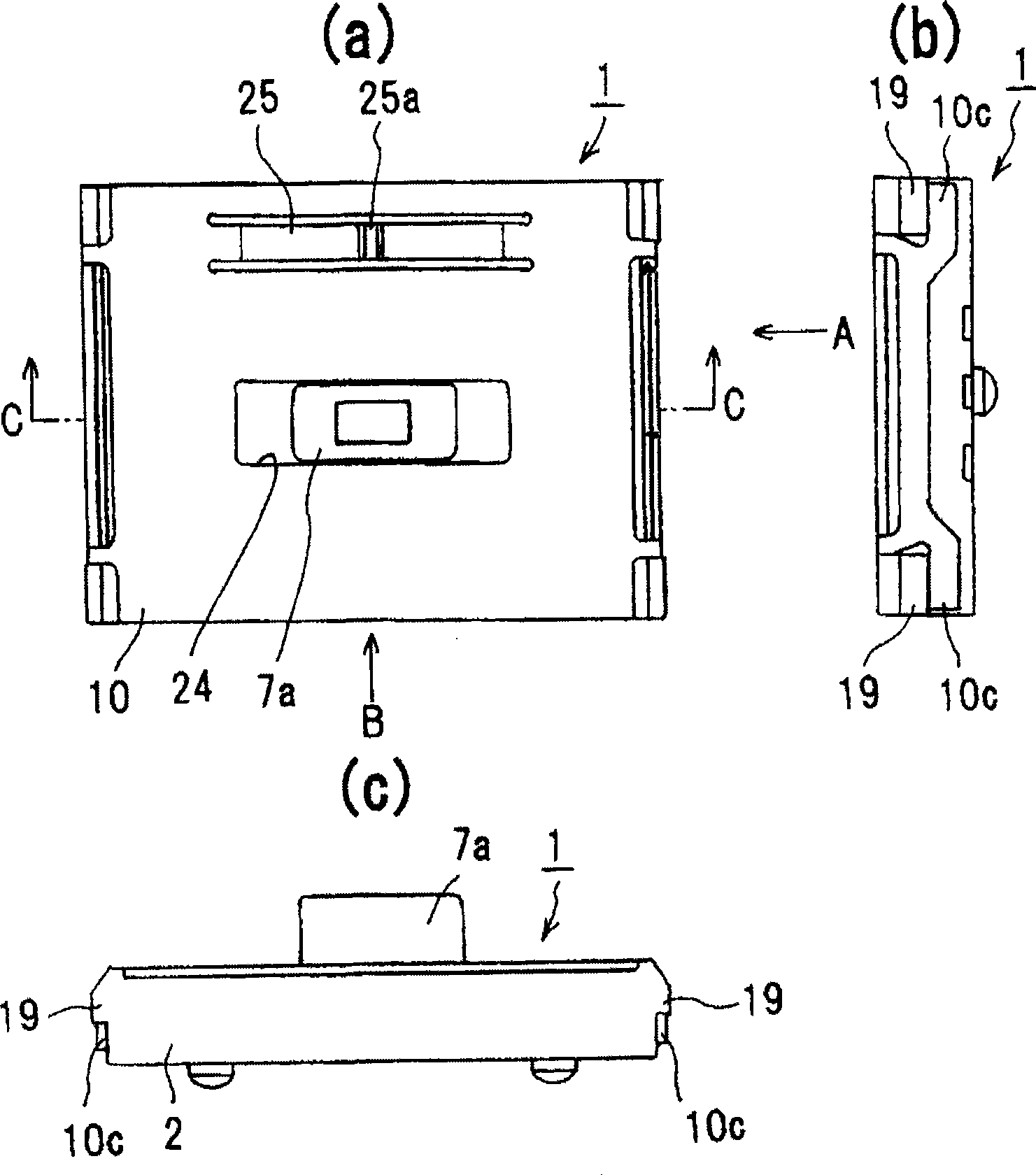
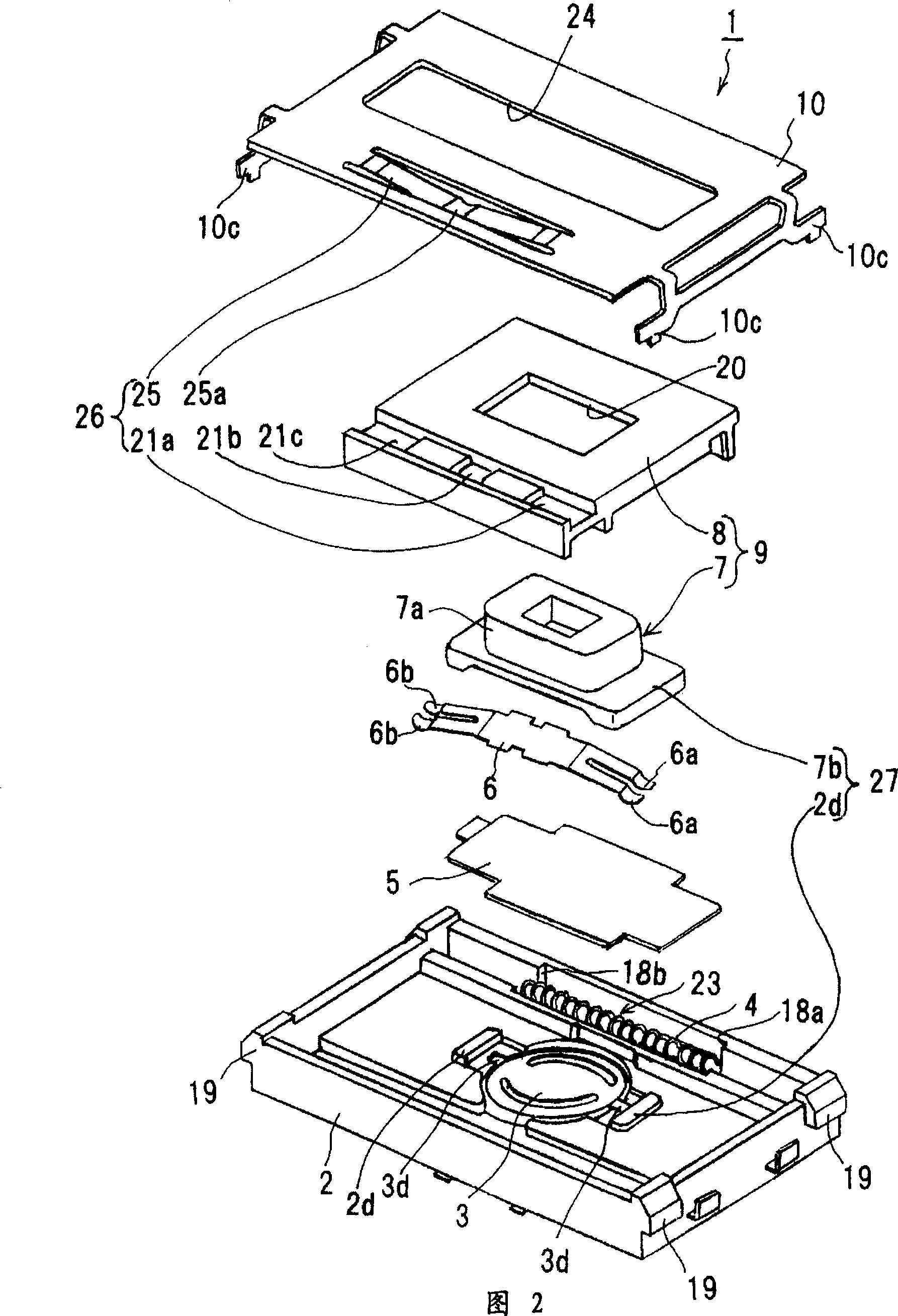
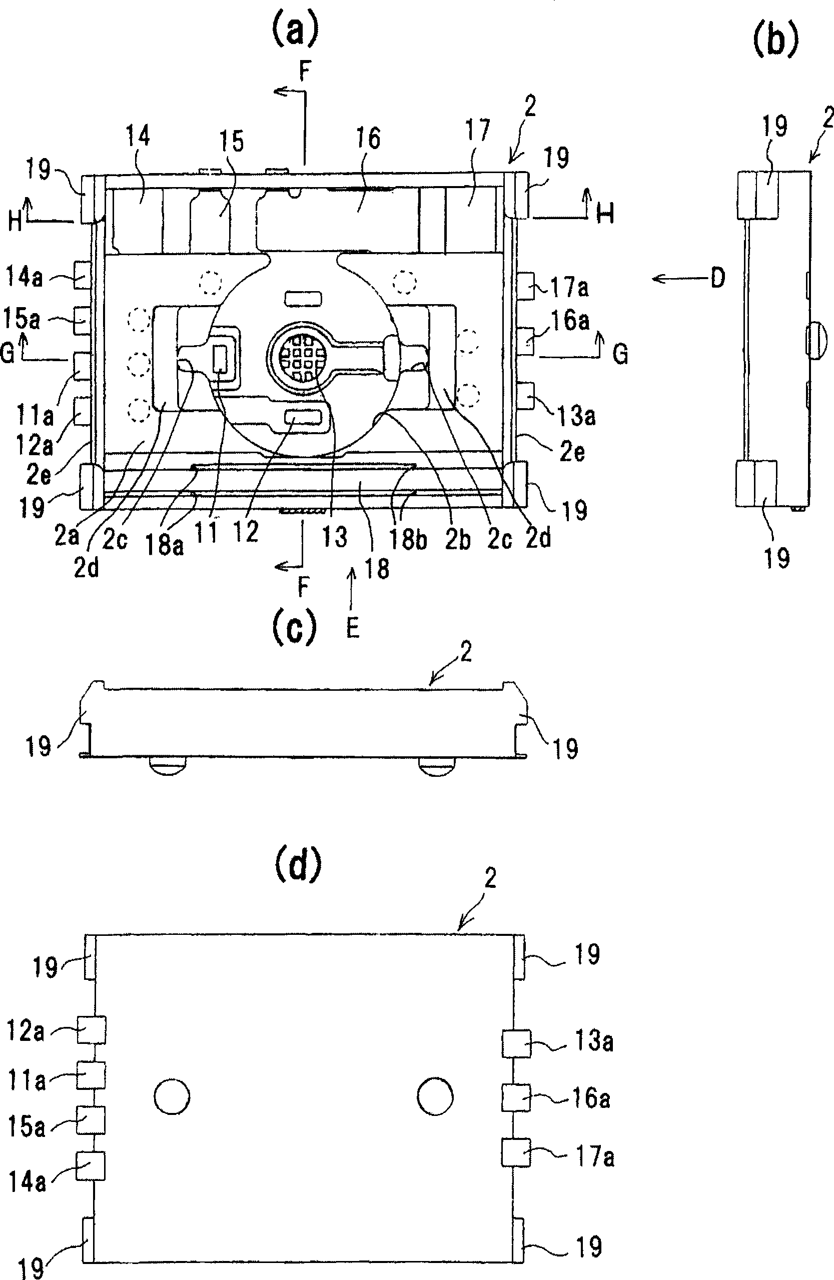
[0043] Hereinafter, embodiments of the present invention will be described in detail with reference to the drawings. This embodiment is suitable for a sliding displacement contact switch with a push switch provided with a two-stage pressing mechanism. figure 1 It is a figure showing the appearance of the sliding contact switch with push switch, and Fig. 2 is an exploded perspective view of main parts of the slide contact switch with push switch, image 3 and Figure 4 It is a figure which shows a base part. First, the structure of the slide-displacement contact switch with push switch related to the present embodiment will be described.

[0044] In Fig. 2, the sliding displacement contact switch 1 with the push switch mainly includes: a base body 2; a butterfly-shaped movable contact piece 3 which constitutes a two-stage pressing mechanism together with a plurality of fixed terminals for pressing described later; The coil spring 4 of the return mechanism 23; the insulating ...


PUM


Abstract

The present invention relates to a transitional slide contact switch with a push-press switch, integrating the mechanism as follow, a slide mechanism having a plurality of slide fixed terminals and a slide contact pin for transferring the connection of the plurality of slide fixed terminals; a press mechanism having a plurality of press fixed terminals and a butterfly movable contact pin facing to the press fixed terminals for transferring the connection of the plurality of press fixed terminals; an operation mechanism having a button for press operation and slide operation, and a slide block that may hold the button pressably and is equipped with a slide contact pin and drives the slide contact pin to slide on the plurality of slide fixed terminals when the button is slidely operated; a self-resetting mechanism for generating a force to reset the button to a neutral position when the button is slidely operated at least in one direction and driving the button and the slide block to reset to the neutral position together by the force when releasing the slide block; and a press limit mechanism for limiting the button when transferring the connection between the slide fixed terminals.

Description

technical field [0001] The present invention relates to a slide contact switch with a push switch, and more particularly to a slide contact switch with a push switch that is small, thin, has excellent operability, and is suitable for mounting on, for example, a digital camera. Background technique [0002] As such prior art, for example, the following push slide displacement contact switch is known. According to this prior art, the sliding contact switch function part and the push switch function part each use a coil spring as a spring member for reset, and are configured as a sliding contact type. Furthermore, it can function as a push switch and a slide-displacement contact switch by one push operation (for example, refer to Patent Document 1: Japanese Patent Application Laid-Open No. 2001-229781). [0003] In the prior art described in Patent Document 1, both the slide contact switch function unit and the push switch function unit are of the sliding contact type. Theref...

Claims


Application Information

Patent Timeline
IPC IPC(8): H01H25/00
Inventor 中村哲也寺下俊彦川口繁实河村乔
Owner MITSUMI ELECTRIC CO LTD
Learn More