Table tennis ball launcher

A table tennis and launcher technology, applied in the field of table tennis launchers, can solve the problems of low variability, complex structure, and single direction of serving

Inactive Publication Date: 2010-09-01
陈兆红
View PDF0 Cites 0 Cited by
  • Summary
  • Abstract
  • Description
  • Claims
  • Application Information

AI Technical Summary

Problems solved by technology

In order to solve this problem, people have invented a table tennis launcher, which can be used to practice catching the ball by oneself, which is more convenient and free, but the existing table tennis launcher has a complex structure, and the direction of serving is single, and the variability is not good. powerful

Method used


Image

  • Table tennis ball launcher
  • Table tennis ball launcher
  • Table tennis ball launcher

Examples


Embodiment 1

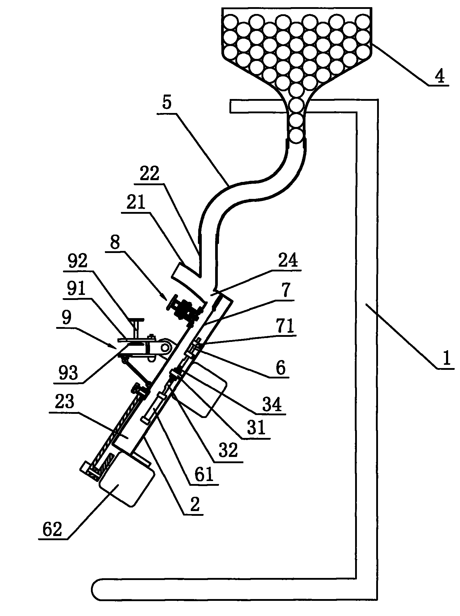
[0023]Embodiment one: as shown in the figure, a kind of table tennis launcher, it comprises base 2, first motor 3, drive plate 32, launching racket 7, support 1 and the storage ball box 4 that is fixedly arranged on support 1, The base 2 is provided with a mutually communicating launch tube 21 and a ball entering tube 22, the ball entering tube 22 communicates with the ball storage box 4 through the connecting hose 5, the base 2 is provided with a first inner cavity 23, the first inner cavity Cavity 23 communicates with ball-injecting pipe 22 through drop-ball hole 24, and the diameter of drop-ball hole 24 is less than the ball diameter of table tennis ball, and first motor 3 is fixedly arranged on base 2, and transmission plate 32 is arranged in the first inner chamber 23, The transmission plate 32 is provided with a second inner cavity 33, the output shaft 31 of the first motor 3 stretches in the second inner cavity 33, and the second inner cavity 33 is provided with a plane ...

Embodiment 2

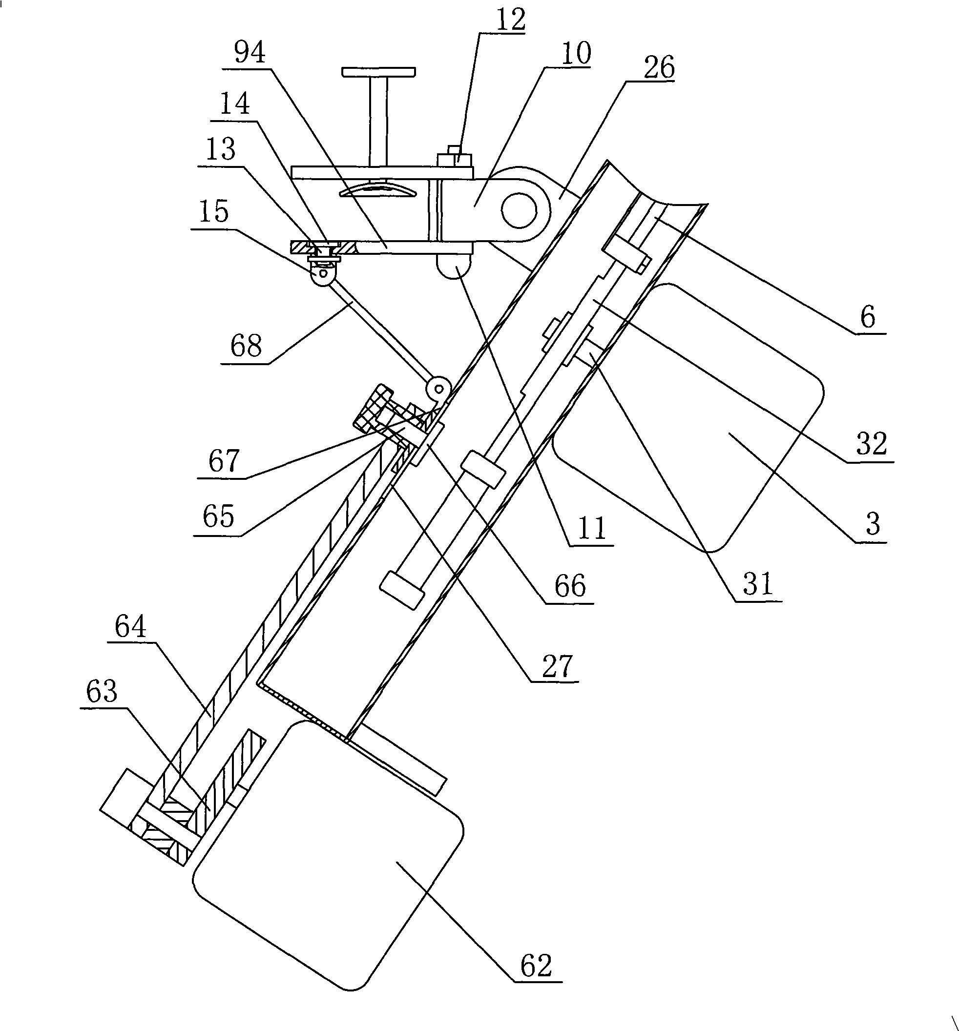
[0024] Embodiment 2: As shown in the figure, other structures are the same as Embodiment 1. The difference is that the fixing screw 92 and suction cup 93 in Embodiment 1 are omitted, and the upper clamping plate 91 and the lower clamping plate 94 are fixedly arranged on the bracket 1, the end of the first connecting rod 11 is fixedly provided with a transmission pulley 16, and the positioning pin 17 passes through the first connecting rod 11 and the first connecting block 10 transversely, so that the gap between the first connecting rod 11 and the first connecting block 10 Can not rotate mutually, the lower clamping plate 94 is provided with a stepper motor 18, the output shaft of the stepper motor 18 passes through the upper clamping plate 91, and the output shaft of the stepper motor 18 is fixedly provided with a driving pulley 19, the driving A transmission belt 20 is arranged between the pulley 19 and the transmission pulley 16, so that the horizontal rotation of the first ...


PUM


Abstract

The invention discloses a table tennis ball launcher, comprising a base, a first motor, a support and a ball storage box which is fixedly arranged on the support. The base is provided with a launching tube and a ball admission tube which are communicated with each other, and the ball admission tube is communicated with the ball storage box by a connection hose. The table tennis ball launcher is characterized in that the base is provided with a first inner chamber, the first inner chamber is intercommunicated with the ball admission tube by a falling hole, an output shaft of the motor extends into the first inner chamber and is provided with a launching bat for beating table tennis balls; the base is provided with at least one roller, and the roller is provided with a depth regulating device. The table tennis ball launcher has the advantage that as the output shaft of the first motor is provided with the launching bat and the base is provided with the roller, when the launching bat passes through the roller in a rotation manner, the launching bat is pressed backwards, and when the launching bat is separated from the roller, and he table tennis balls falling into the falling hole are bounced by rebounding of the launching bat, and the roller is provided with the depth regulating device which can regulate the depth of the roller extending into the first inner chamber, so as to regulate force of launching the table tennis balls by controlling bound force of the launching bat.

Description

technical field [0001] The invention relates to a table tennis auxiliary exercise device, in particular to a table tennis launcher. Background technique [0002] Table tennis is our national sport in China, and it is very popular in national sports, but athletes can achieve impressive results in international competitions and their usual training is inseparable. Athletes basically rely on two people to practice against each other in training. The strength of the two sides is different. Athletes with good skills may not be able to achieve the training effect they want, and the training time needs to be arranged by two people. Not free in time either. In order to solve this problem, people have invented a table tennis launcher, which can be used to practice catching the ball by oneself, which is more convenient and free, but the existing table tennis launcher has a complicated structure, and the direction of serving is single, and the variability is not good. powerful. Con...

Claims


Application Information

Patent Timeline
Patent Type & Authority Patents(China)
IPC IPC(8): A63B69/40A63B69/00
Inventor 陈兆红
Owner 陈兆红
Why Eureka
Try Eureka