
Three-dimensional auxiliary two-dimensional pattern drafting method

A two-dimensional graphics and three-dimensional technology, applied in the field of digital entertainment, to achieve the effect of accelerating the animation production process, expanding the source, and enriching the picture effect

Inactive Publication Date: 2011-10-19
MUDANJIANG NEWS MEDIA GROUP
View PDF0 Cites 0 Cited by
  • Summary
  • Abstract
  • Description
  • Claims
  • Application Information

AI Technical Summary

Problems solved by technology

[0005] The purpose of the present invention is to solve the problem that the existing production software cannot automatically determine which parts of the character will be blocked when the viewing angle is changed, and to provide a three-dimensional assisted two-dimensional graphics drawing method

Method used


Image

  • Three-dimensional auxiliary two-dimensional pattern drafting method
  • Three-dimensional auxiliary two-dimensional pattern drafting method
  • Three-dimensional auxiliary two-dimensional pattern drafting method

Examples


specific Embodiment approach 1

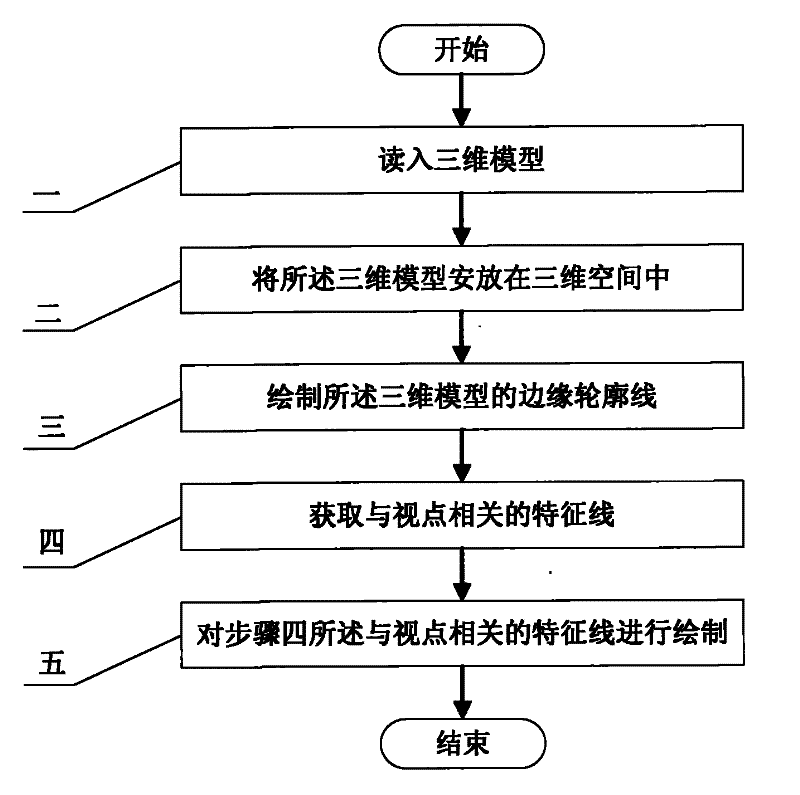
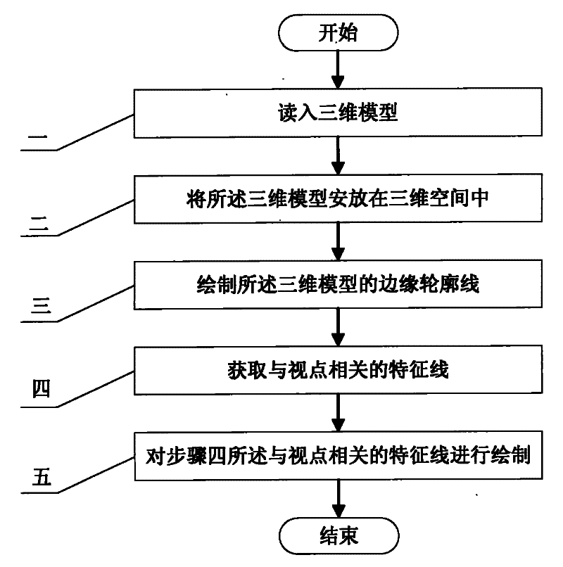
[0020] Specific implementation mode one: the following combination figure 1 Describe this embodiment, this embodiment is a three-dimensional assisted two-dimensional graphics drawing method, the steps to realize this embodiment include:

[0021] Step 1, read in the 3D model, obtain the normal vector of the vertex of the 3D model, the principal curvature of the vertex, the Gaussian curvature of the vertex and the direction of the principal curvature of the vertex;

[0022] Step 2. Place the 3D model in the 3D space, allowing translation and rotation of the position of the 3D model. The user can easily determine the spatial position relationship and viewing angle between the 3D models, and place the 3D model The model is projected in the 2D animation scene;

[0023] Step 3, drawing the edge outline of the three-dimensional model;

[0024] Step 4, obtaining feature lines related to the viewpoint;

[0025] Step 5, drawing the feature line related to the viewpoint described in s...

specific Embodiment approach 2

[0027] Specific embodiment two: the difference between this embodiment and embodiment one is that the method of drawing the edge contour line of the three-dimensional model in step three is: dividing the three-dimensional model into a plurality of triangles, if the three triangles of each triangle normals of vertices with sight dot product different numbers, use the Hermite interpolation method to obtain the The straight line is a part of the edge contour of the three-dimensional model, and the dot product of all the three vertices of the triangle obtained by different numbers The straight lines are drawn together to form the edge outline of the three-dimensional model, and other steps and technical solutions are the same as those in Embodiment 1.

specific Embodiment approach 3

[0028] Specific embodiment three: the difference between this embodiment and embodiment two is that the dot product in the triangular slice is obtained by using the Hermite interpolation method The method of the straight line is: utilize the following formula val(t)=[2(val 0 -val 1 )+d 0 +d 1 ]×t 3 +[3(val 1 -val 0 )-2d 0 -d 1 ]×t 2 +d 0 ×t+val 0 Get Triangle V 0 Vertex, V 1 dot product of vertices , where t is the interpolation parameter, and t∈[0,1], val 0 is V 0 dot product of vertices, val 1 is V 1 dot product of vertices, d 0 and d 1 are V 0 Vertex and V 1 The first order derivative of the curvature in the direction of the vertex's apparent projection, and other steps and technical solutions are the same as those in Embodiment 2.


PUM


Abstract

The invention relates to a method for drawing a three-dimensionally assisted two-dimensional graphic, which relates to a drawing method applying a three-dimensional model to a two-dimensional animation and belongs to the field of digital entertainment. The method aims at solving the problem that the prior software cannot automatically determine which parts of a role will be covered under a condition that the visual angle is changed. The method comprises the following steps: 1, reading in the three-dimensional model, and acquiring a vertex normal vector, a vertex principal curvature, a vertex Gaussian curvature and the direction of the vertex principal curvature of the three-dimensional model; 2, placing the three-dimensional model in a three-dimensional space; 3, drawing an edge contour line of the three-dimensional model; 4, acquiring a characteristic line related to a viewpoint; and 5, drawing the characteristic line related to the viewpoint in the step 4. Through the combination ofthe two-dimensional animation and a three-dimensional animation, the visual effect is enriched, and the source of animation raw data is expanded.

Description

technical field [0001] The invention relates to a drawing method for applying a three-dimensional model to a two-dimensional animation, belonging to the field of digital entertainment. Background technique [0002] At present, the computer-aided two-dimensional animation production system mainly focuses on realizing some production steps in traditional manual animation by means of computer, and its main algorithm is key frame interpolation. However, the existing methods for automatically generating intermediate images have relatively large limitations, requiring the objects between key images to be continuous both geometrically and temporally. Since the 2D animation lacks the 3D depth information of the scene, how to express the occlusion relationship between the characters and the lines inside the characters is a difficult problem. In mainstream software products, such as Toonz, Toonboom, and Retas, animators are required to carefully determine the line correspondence betw...

Claims


Application Information

Patent Timeline
Patent Type & Authority Patents(China)
IPC IPC(8): G06T13/00G06T13/80
Inventor 邱兆文穆雪峰高岩周俊伟
Owner MUDANJIANG NEWS MEDIA GROUP
Learn More