
Microstrip filter

A microstrip filter and microstrip line technology, which is applied in the directions of waveguide devices, electrical components, circuits, etc., can solve the problems of inconvenient application and large size of the microstrip filter, and achieve simple structure, small size, good The effect of performance

Inactive Publication Date: 2009-05-20
NEW H3C TECH CO LTD
View PDF2 Cites 12 Cited by
  • Summary
  • Abstract
  • Description
  • Claims
  • Application Information

AI Technical Summary

Problems solved by technology

The size of the microstrip filter is relatively large, and it is not very convenient to apply in some occasions

Method used


Image

  • Microstrip filter
  • Microstrip filter
  • Microstrip filter

Examples


Embodiment Construction

[0015] The microstrip filter of the present invention is mainly composed of a metal plate with a cross-shaped capacitive effect connected in parallel and two defective grounding structures with inductive effect connected in series.

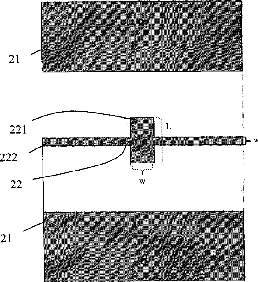
[0016] Figure 2a and Figure 2b They are the top-layer and bottom-layer structure diagrams of the microstrip filter in the best embodiment of the present invention, respectively. image 3 It is the three-dimensional structural diagram of this embodiment. Such as Figure 2a and 2b and image 3 As shown, the top layer of the microstrip filter 1 includes a cross open microstrip line 22 with capacitive effect, and the cross open microstrip line 22 can be made of metal such as copper. The cross open microstrip line 22 includes vertical lines 221 and horizontal lines 222 . The width w of the horizontal line corresponds to the characteristic impedance, where w is 18 mils (1 mil=0.0254 mm), corresponding to a characteristic impedance of 50 ohms, an...


PUM


Abstract

The invention provides a micro-strip filter with a novel defected ground structure. The micro-strip filter is produced by a printed circuit board, a first layer of the printed circuit board comprises a cross open-circuit micro-strip line with capacity effect, a second layer comprises a first defected ground unit and a second defected ground unit which have inductive effect, the first defected ground unit and the second defected ground unit are axially symmetrical along the longitudinal axis of the circuit board and comprise a first E-shaped slot and a second E-shaped slot respectively, openings of the first E-shaped slot and the second E-shaped slot are oppositely arranged and are axially symmetrical along the lateral axis of the circuit board, and the cross open-circuit micro-strip line of the first layer is relatively positioned between the two defected ground units of the second layer. The micro-strip filter with the novel defected ground structure has smaller size and a simpler structure, and has good performance on the working band.

Description

technical field [0001] The invention relates to the field of microstrip filters, in particular to a defected ground structure (DGS, Defected Ground Structure) microstrip low-pass filter. Background technique [0002] A filter is a frequency-selective circuit that allows signals of some frequencies to pass through smoothly, while signals of other frequencies are largely suppressed. Filters can be divided into low-pass filters, high-pass filters, band-pass filters and band-stop filters according to the frequency band of the passing signal. According to the structure type, it can be divided into microstrip filter, coaxial filter, waveguide filter and so on. Figure 1a and Figure 1b A microstrip filter is disclosed. The filter is divided into a top layer 11 and a bottom layer 12. The metal sheet on the top layer 11 is etched to form a symmetrical irregular pattern 13, and the bottom layer 12 is a grounded metal sheet. The size of the microstrip filter is relatively large, an...

Claims


Application Information

Patent Timeline
IPC IPC(8): H01P1/203
Inventor 杨伟
Owner NEW H3C TECH CO LTD
Learn More