CD read-write equipment and method for manufacturing and regulating/controlling the optical head of the same
A technology for reading and writing equipment and manufacturing methods, which is applied in the fields of optical head manufacturing, optical recording head, head configuration/installation, etc., and can solve problems such as damage to the optical head, lack of a specific design for implementation, and obstruction of the optical disc from jacking up and rotating.
- Summary
- Abstract
- Description
- Claims
- Application Information
AI Technical Summary
Problems solved by technology
Method used
Image
Examples
Embodiment 1
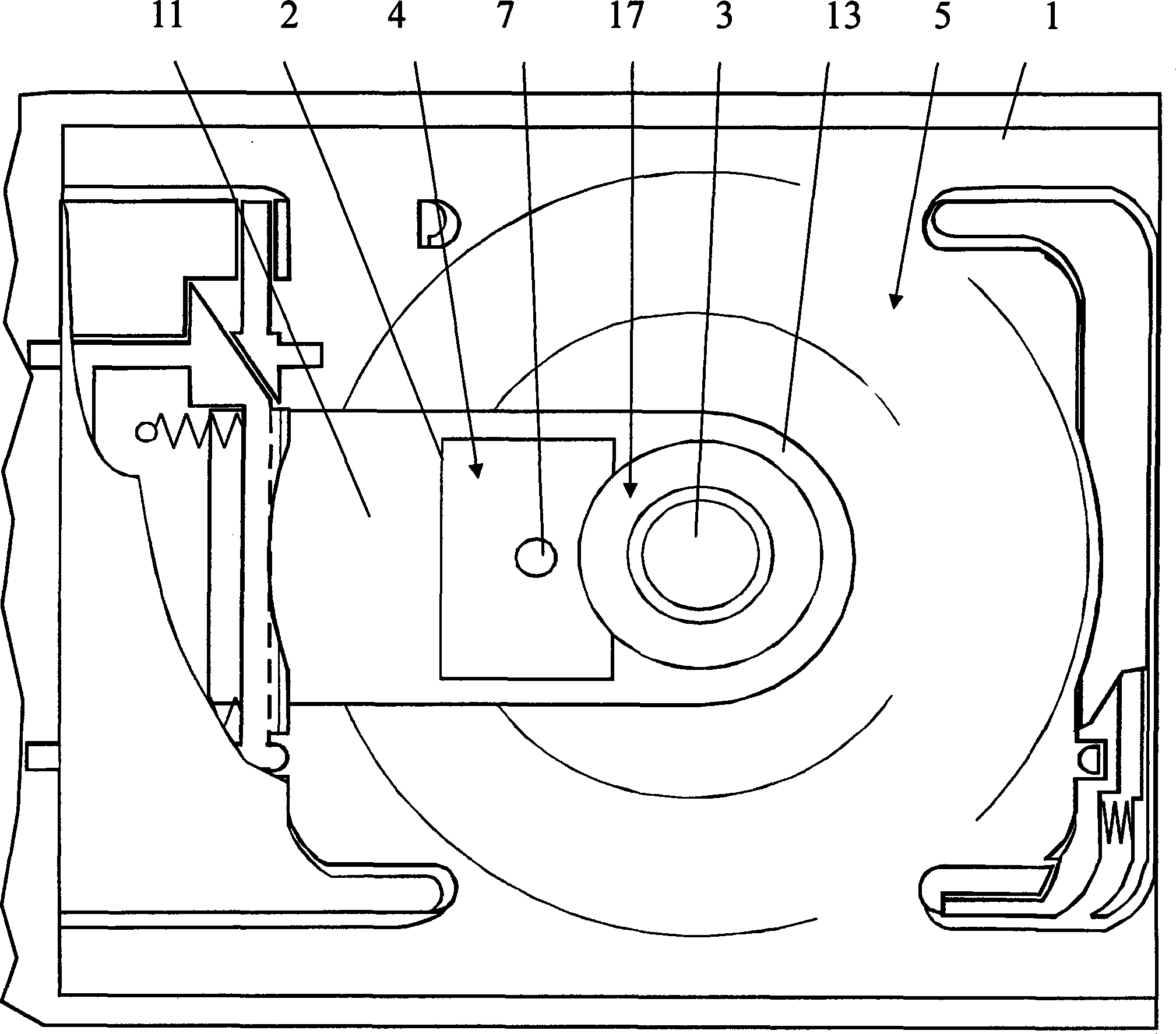
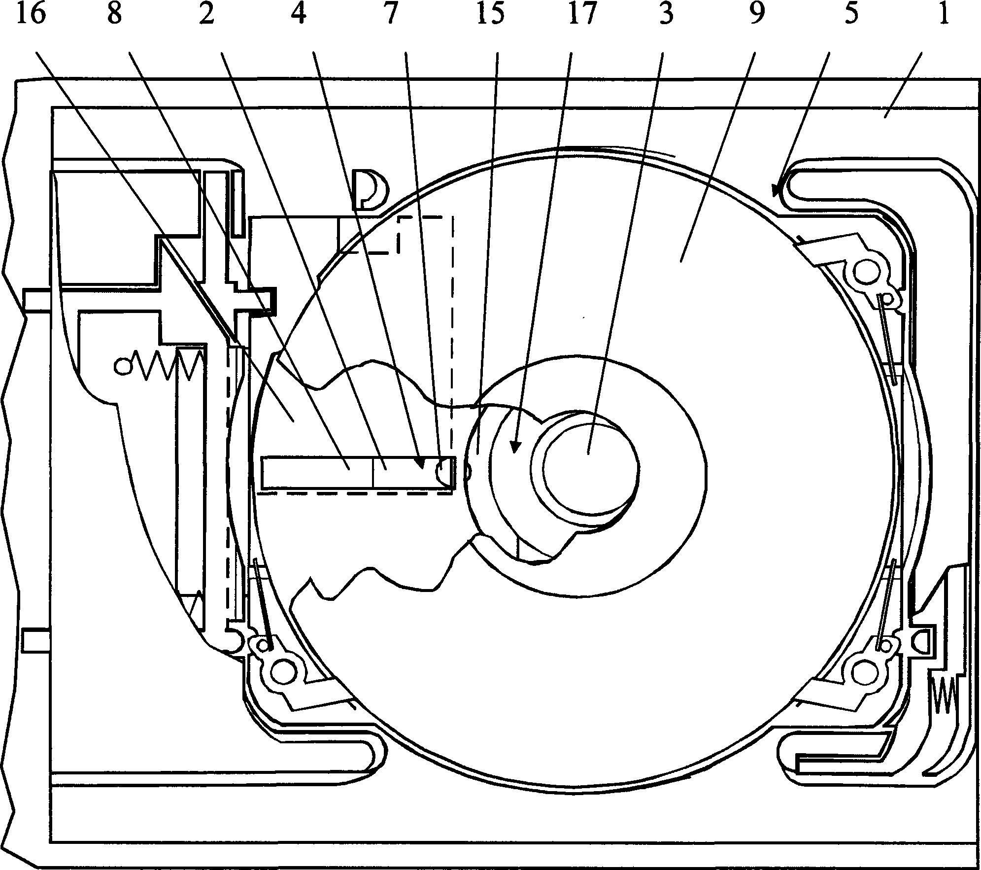
[0055] figure 1 , 2 , 3, and 4 are schematic diagrams of the appearance of the first preferred solution of the present invention.
[0056] The optical disc reading and writing device of the present invention comprises an optical disc bracket 1 , an optical head 2 , and a rotating motor head 3 . The optical disc tray 1 includes an optical head read-write slot 11 and a rotary motor head hole 13. In order to simplify the manufacturing process, the optical head read-write slot 11 of the optical disc tray and the rotary motor head hole 13 are connected as one, and the optical head 2 and the rotary motor head 3 Set on the slide rail 14 of the power unit below the disc tray 1, the optical head 2 can slide back and forth along the slide rail 14, the rotating motor head 3 is fixed on one end of the slide rail 14, the optical head 2 and the rotating motor head 3 can pass through the disc tray 1, the power unit below implements lifting to facilitate cooperation with the optical disc tr...
Embodiment 2
[0063] The similarities with Embodiment 1 will not be described in detail. The difference is mainly that this embodiment adopts the second manufacturing control method applicable to the optical head of the first preferred solution:
[0064] In order to reduce the focusing distance of the condenser lens 7 of the optical head as much as possible, so as to reduce the manufacturing process and cost of the optical head 2, and also reduce the overall thickness of the optical disc reading and writing device as much as possible.
[0065] So also can reduce the height of rotating motor head 3 a value, the reduction value of rotating motor head 3 is equal to, the distance 1 millimeter that optical head 2 lowers, subtracts the thickness 0.8 of the optical disc groove 16 of the middle part of single-sided disc guard case 6 disc loading part mm, the resulting value is 0.2 mm, and the value greater than 0 is a desirable value, so the connection structure between the rotating motor head 3 and...
Embodiment 3
[0068] The similarities with Embodiment 1 will not be repeated, and the difference mainly lies in that this embodiment adopts one of the third manufacturing control methods applicable to the optical head of the first preferred solution:
[0069] The single-sided disc protection case 6 adopted in the present embodiment has a thickness of 1.2 millimeters in the disc groove 16 of the disc adorning part in the middle.
[0070] When manufacturing the optical head 2, the distance that the optical head 2 is lowered is 1 millimeter, which is less than the thickness 1.2 millimeters of the optical disc groove 16 of the disc loading part in the middle of the single-sided disc guard case 6;
[0071] So at first increase the height value of rotating motor head 3, the heightening value of rotating motor head 3 is equal to, the thickness 1.2 millimeters of the optical disc groove 16 of the middle part of single-sided disc guard case 6, minus the distance 1 millimeter that optical head 2 lower...
PUM
| Property | Measurement | Unit |
|---|---|---|
| thickness | aaaaa | aaaaa |
Abstract
Description
Claims
Application Information
 - R&D
- Intellectual Property
- Life Sciences
- Materials
- Tech Scout
- Unparalleled Data Quality
- Higher Quality Content
- 60% Fewer Hallucinations
Browse by: Latest US Patents, China's latest patents, Technical Efficacy Thesaurus, Application Domain, Technology Topic, Popular Technical Reports.
© 2025 PatSnap. All rights reserved.Legal|Privacy policy|Modern Slavery Act Transparency Statement|Sitemap|About US| Contact US: help@patsnap.com


