Stitch pulsation welding device

A pulse welding and pin technology, applied in welding equipment, arc welding equipment, manufacturing tools, etc., can solve the problems of large indicating workload and difficult combination of welding current and welding time, so as to reduce indicating workload and shorten production takt time. Effect

Inactive Publication Date: 2009-05-20
DAIHEN CORP
View PDF6 Cites 2 Cited by
  • Summary
  • Abstract
  • Description
  • Claims
  • Application Information

AI Technical Summary

Problems solved by technology

[0019] That is, because the combination of welding current, welding voltage and welding time is very difficult, and the moving distance needs to be set accordingly according to their combination, there is a problem that a large amount of indicating workload is spent in order to form an ideal weld shape.

Method used


Image

  • Stitch pulsation welding device
  • Stitch pulsation welding device
  • Stitch pulsation welding device

Examples


Embodiment Construction

[0040] Hereinafter, embodiments of the invention will be described based on examples with reference to the drawings.

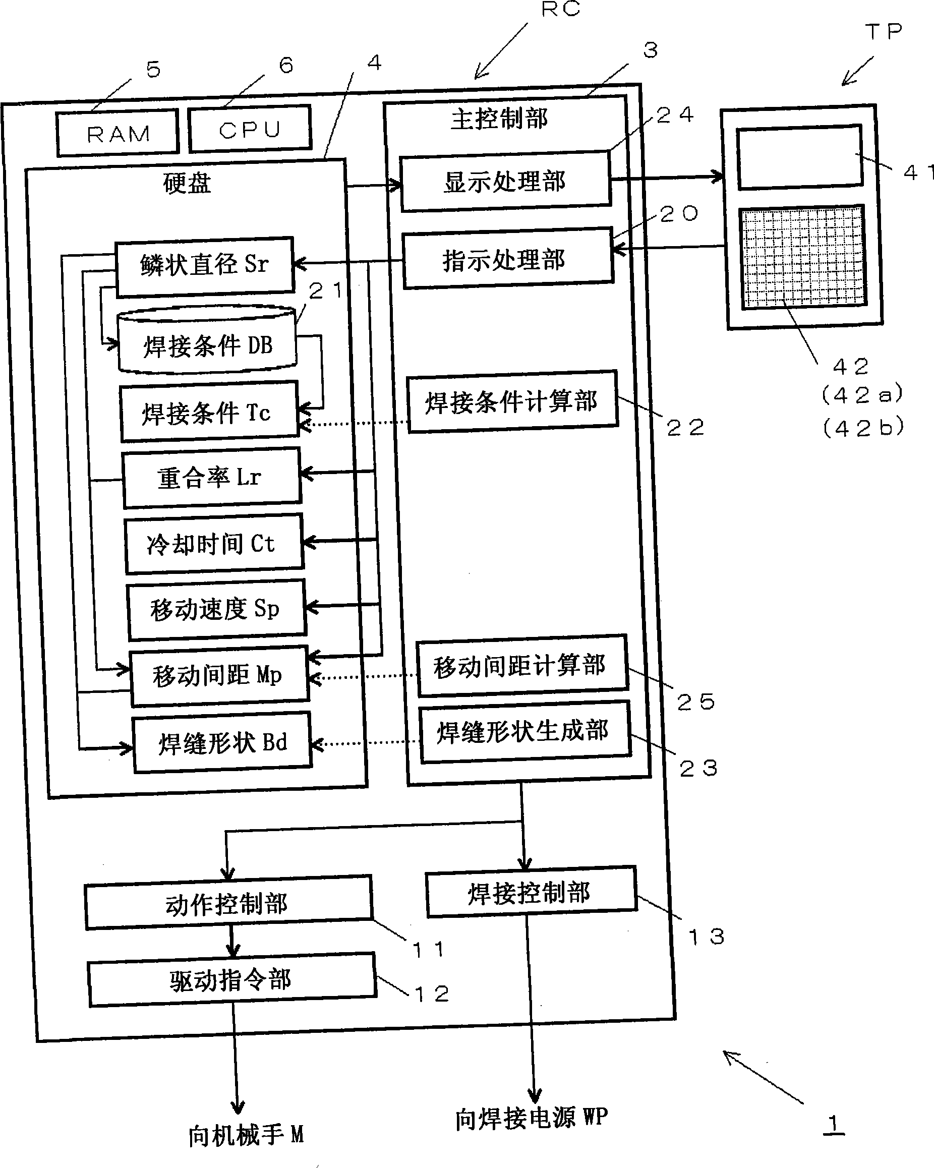
[0041] figure 1 It is a block diagram of the stitch pulse welding device 1 of the present invention. In this figure, with the prior art Figure 5 The difference lies in the robot controller RC and the indicator panel TP as operating unit. In addition, not shown and omitted Figure 4 The manipulator M, the welding power source WP, the welding wire reel 56, the gas tank 58, etc. described in Hereinafter, the robot controller RC and the indicator panel TP constituting the main parts of the present invention will be described.

[0042] The robot control device RC is a device for controlling the welding operation of the manipulator M, and includes: a main control unit 3 serving as the center; performing calculations on the trajectory of the manipulator M, etc., and outputting the calculation results as drive signals to the drive command unit 12 A motion contro...


PUM

PropertyMeasurementUnit
lengthaaaaaaaaaa

Abstract

The invention provides a stitch pulse welding device which automatically sets a welding condition being needed by designating the anticipate shape of a welding seam. The stitch pulse welding device (1) produces an electric arc under a state when a welding torch is stopped, the electric arc is stopped after prescriptive welding time, the welding torch moves repeatedly in the welding direction and begins to be ignited until moving away from the electric arc with a prescriptive moving distance, then the electric arc is produced again, a welding mark, namely squamous epithelium formed in one production of the electric arc is coincided, and the welding seam is formed on a workpiece. The stitch pulse welding device is provided with a welding condition database part (21) which stores the data of corresponding relation between the welding condition (Tc) and a squamous epithelium diameter value (Sr), a welding condition calculation part (22), which takes the squamous epithelium diameter value (Sr) as input and calculates the welding condition (Tc) by the welding condition database part (21), and a moving distance calculation part (25) which automatically calculates moving distance (Mp) through a set squamous epithelium coincidence rate (Lr).

Description

technical field [0001] The present invention relates to a stitch pulse welding device that performs welding while suppressing the influence of heat on a base material of a thin plate to a minimum. Background technique [0002] The so-called stitch pulse welding method is a welding method that minimizes the thermal influence on the base metal of the thin plate by controlling the heating and cooling during welding. It is a welding method aimed at the automation of thin plate welding, and can improve the appearance of welding and reduce the amount of welding deformation compared with conventional thin plate welding (for example, refer to Patent Document 1). [0003] Patent Document 1 discloses a method of melting a base material by generating an arc only for a predetermined time while the torch is stopped, and then stopping the arc and moving the torch after the set time elapses. The point where the arc restarts to the outer peripheral side of the fusion zone. Hereinafter, th...

Claims


Application Information

Patent Timeline
Patent Type & Authority Applications(China)
IPC IPC(8): B23K9/09
Inventor 广田周吾上园敏郎中津川勇二
Owner DAIHEN CORP
Why Eureka
Try Eureka