
Test method and apparatus for pin element

A test method and technology of a test device, applied in the direction of measurement device, measurement of electricity, measurement of electric variables, etc., can solve the problems of poor contact, large application, pressure damage to the object 9 under test, etc., to reduce pressure and improve contact. , the effect of reducing the probability of damage due to pressure

Active Publication Date: 2009-05-13
UNIVERSAL SCIENTIFIC INDUSTRIAL (SHANGHAI) CO LTD
View PDF0 Cites 2 Cited by
  • Summary
  • Abstract
  • Description
  • Claims
  • Application Information

AI Technical Summary

Problems solved by technology

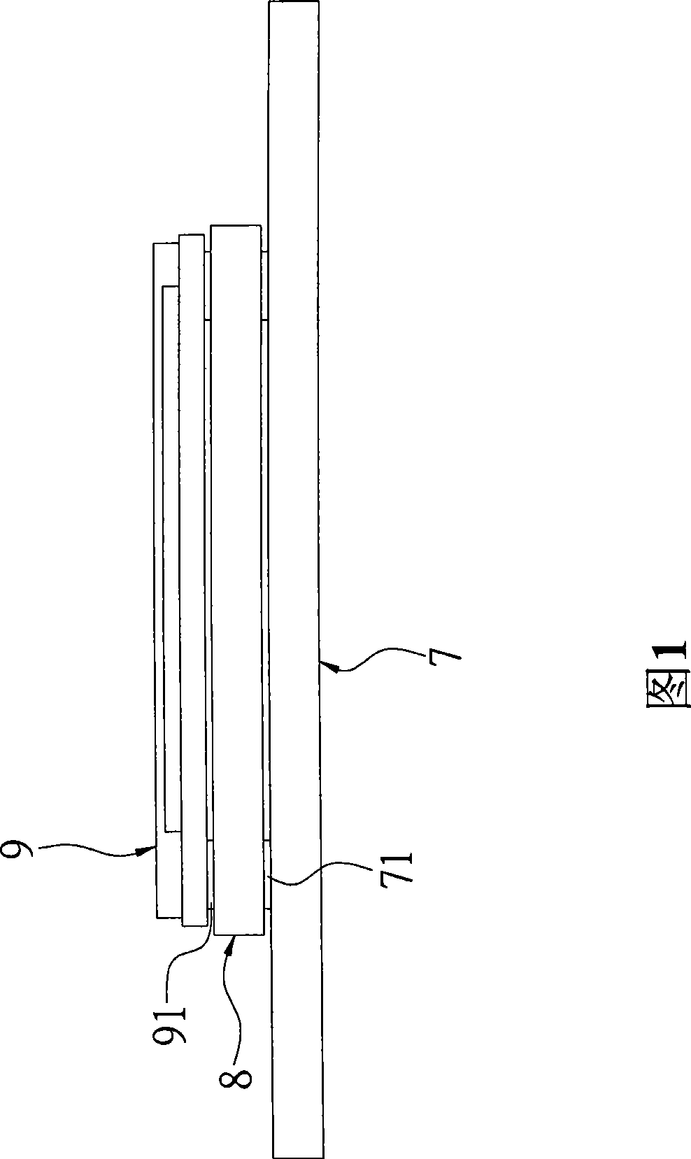
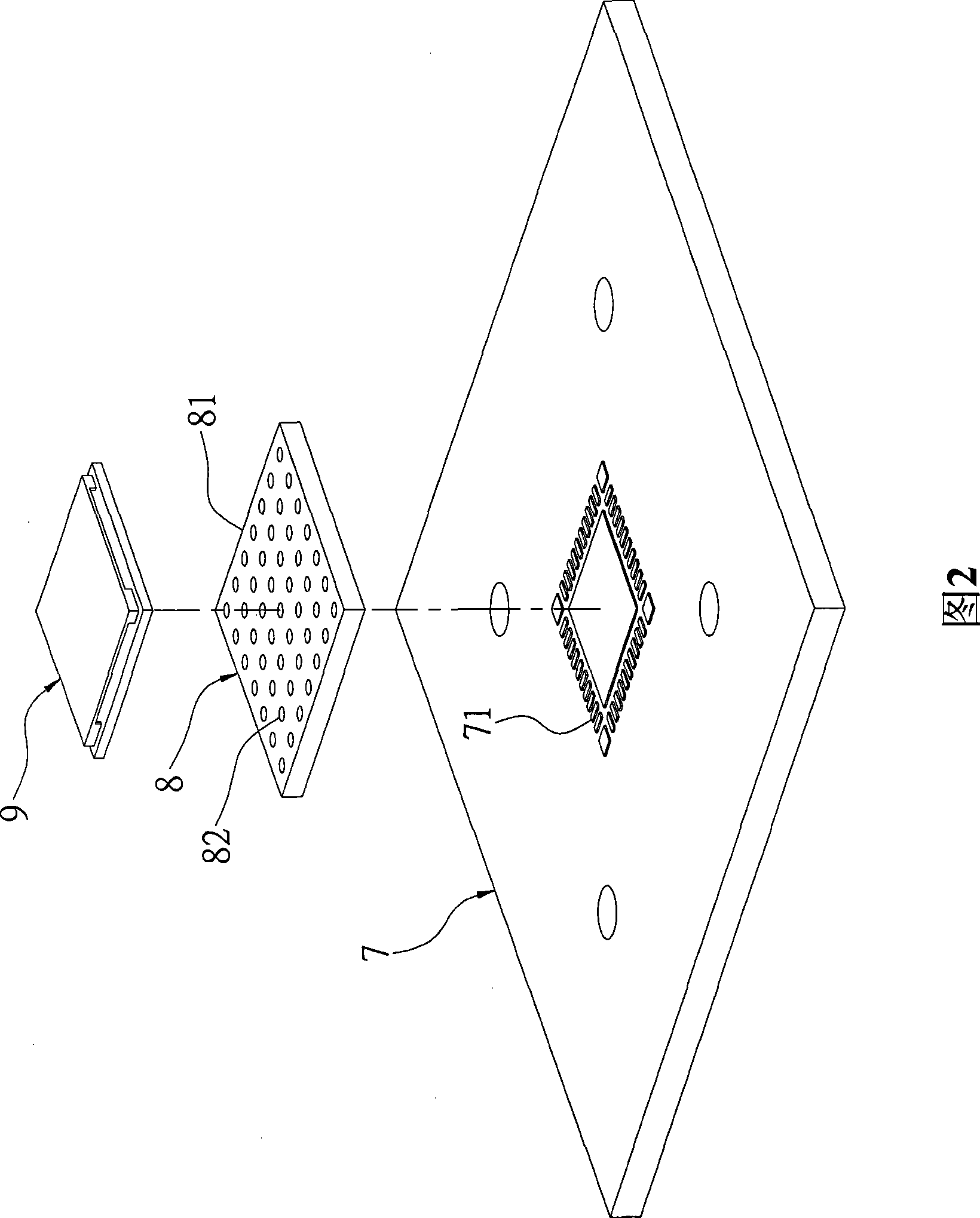
However, the conductive gasket 8 has poor contact with the object under test 9 with a flat surface, and a relatively large pressure must be applied to the object under test 9 during the test. If it is applied to an object under test 9 on a ceramic substrate, there will be pressure damage problem

Method used


Image

  • Test method and apparatus for pin element
  • Test method and apparatus for pin element
  • Test method and apparatus for pin element

Examples


Embodiment Construction

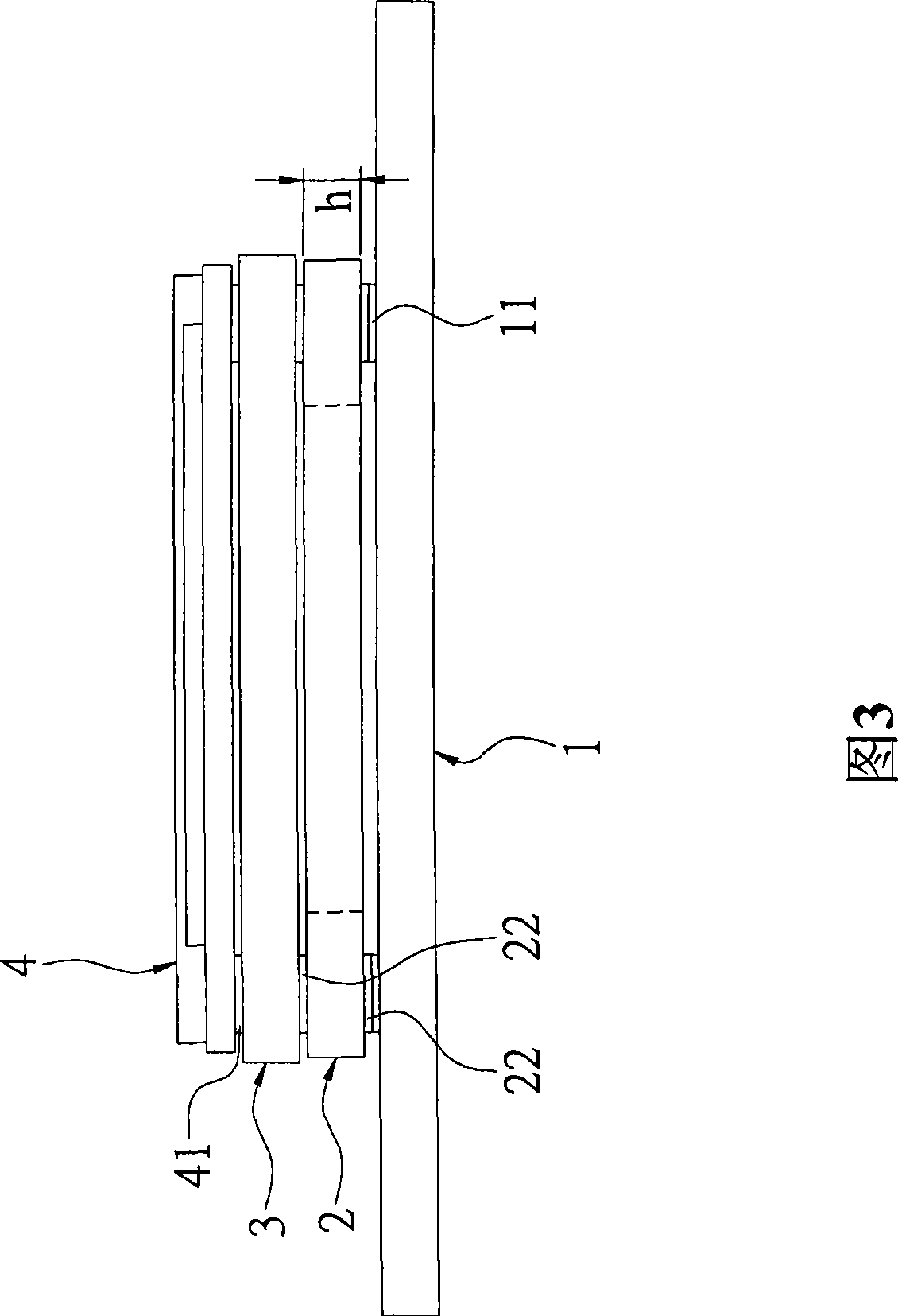
[0034] Please refer to Fig. 3 to Fig. 5, the present invention provides a kind of testing method of pin component, especially a kind of testing method suitable for the electronic part (under test) of LGA pin form, comprise steps as follows:

[0035] (1) Firstly, a test carrier board 1 is provided. The top surface of the test carrier board 1 has a plurality of test contacts 11 corresponding to the plurality of pins 41 on the bottom surface of the object under test 4 .

[0036] (2) A test sub-board 2 is provided. A square hollow part 21 is formed inside the test sub-board 2. The hollow part 21 penetrates from the top surface of the test sub-board 2 to the bottom surface. The test sub-board 2 is placed on the hollow part. 21 is provided with a plurality of conductors 22 at the periphery, the conductors 22 correspond to the test contacts 11, and the conductors 22 penetrate from the top surface of the test sub-board 2 to the bottom surface; in this embodiment, The test sub-board 2 ...


PUM


Abstract

The invention relates to a test method of a pin element. The method comprises the following steps: providing a test support board which is provided with a plurality of test contacts; providing a test daughter board which is provided with a plurality of conductors throughout the top surface of the test daughter board to the bottom surface of the test daughter board, wherein, drop height forms on the test daughter board, and the test daughter board is arranged on the test support board, and the conductors are correspondingly contacted with the test contacts; arranging a conductive gasket on the test daughter board, wherein, the conductive gasket correspondingly contacts the conductors of the test daughter board; and arranging an object to be tested on the conductive gasket, wherein, the object to be tested is provided with a plurality of pins which contacts the conductive gasket, the object to be tested is pressed so that the pins of the object to be tested, the conductive gasket, the conductors of the test daughter board are electrically connected with the test contacts of the test support board to test the object to be tested. The invention further provides a test device for the pin element.

Description

technical field [0001] The invention relates to a testing method and device, in particular to a testing method and device for electronic parts in the form of LGA pins, that is, a testing method and device for pin components. Background technique [0002] Generally, test fixtures for SMT parts (objects to be tested) in the form of LGA (Land Grid Array) pins mostly use probes or conductive pads to electrically connect the objects to be tested and the test carrier. Although the use of probes has better contact performance, they need to be replaced frequently because they are easily damaged, and the cost is relatively high. The cost of using a conductive gasket is lower than that of a probe, and it is not easy to be damaged, but it has poor contact with the object under test with a flat surface, and it needs to apply a large pressure to the object under test during the test. [0003] Please refer to Fig. 1 and Fig. 2, disclose a kind of existing test device that uses conductive...

Claims


Application Information

Patent Timeline
IPC IPC(8): G01R31/00G01R1/02G01R1/06
Inventor 李冠兴
Owner UNIVERSAL SCIENTIFIC INDUSTRIAL (SHANGHAI) CO LTD
Learn More