
Electro-optical polarization spectrometry microscope

A technology of polarization spectrum and microscopy, applied in the direction of polarization influence characteristics, etc., can solve the problems of judgment error of experimental results, complex structure, troublesome operation, etc., and achieve the effect of improving measurement accuracy and stability, improving technical level, and easy operation

Inactive Publication Date: 2010-08-11
ZHEJIANG UNIV
View PDF0 Cites 0 Cited by
  • Summary
  • Abstract
  • Description
  • Claims
  • Application Information

AI Technical Summary

Problems solved by technology

This structure cannot capture full polarization information that can accurately characterize physiological properties
However, relying on mechanical rotation to change the polarization angle, continuously recording data and real-time processing to obtain full polarization information requires high data accuracy. error in judgment
Although other high-end microscopes can directly realize the functions of this patent and have higher precision, the equipment of these microscopes is of high value, complex in structure, cumbersome to operate, and requires a lot of expenses for maintenance. Many researchers cannot conveniently use these microscopes for various reasons. The equipment observes the microstructure in the sample, so it cannot be widely used for the time being

Method used

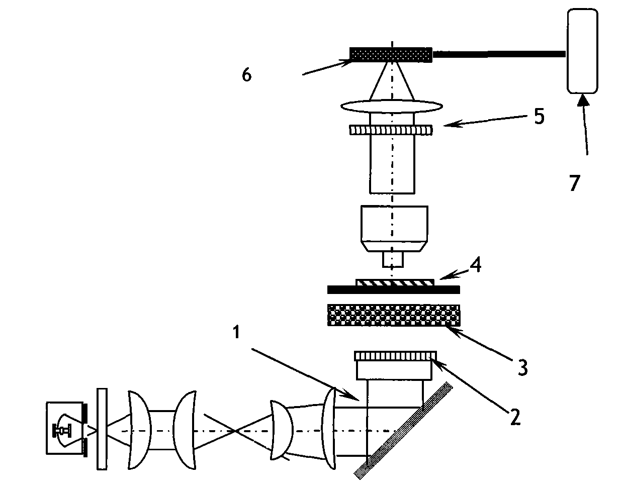

Image

  • Electro-optical polarization spectrometry microscope
  • Electro-optical polarization spectrometry microscope
  • Electro-optical polarization spectrometry microscope

Examples


Embodiment Construction

[0017] The present invention will be further described below in conjunction with drawings and embodiments.

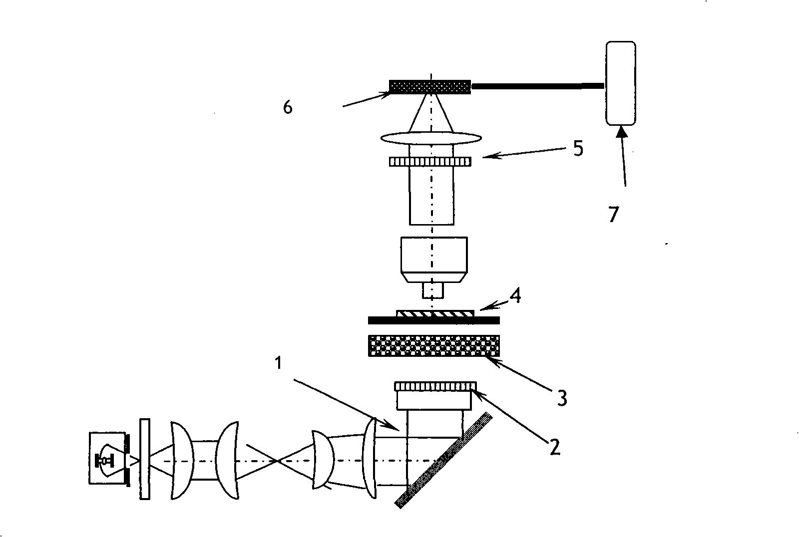
[0018] As shown in Figure 1, it includes a light source system, a fixed linear polarizer 2, a fixed electro-optical rotator 3, a polarizer 5, a charge-coupled device CCD 6, and a computer 7; the incident light 1 emitted by the light source system is reflected by a mirror and enters the The fixed linear polarizer 2 with polarization function under the stage, then passes through the fixed electro-optic rotator 3 with the function of changing the linear polarization angle, and then the light after passing through the sample 4 to be observed on the stage enters the analyzer 5 After transmission, the polarization signal is received by the charge-coupled device CCD6, and then stored by the computer 7 to display the polarization spectrum image.

[0019] The working principle of the present invention is as follows:

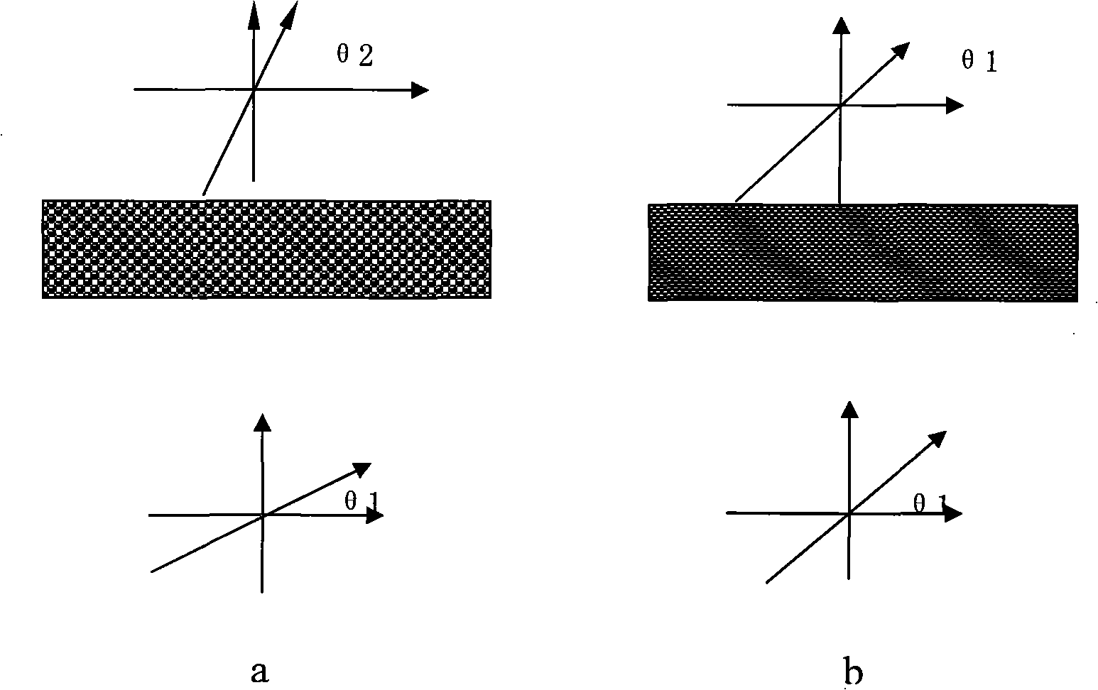
[0020] The following uses onion epidermal cells as an exampl...


PUM


Abstract

The invention discloses an electric light type polarization spectrum measuring microscope which is based on an ordinary optical microscope structure and is added with a fixed linear polarizer, a fixed electric light polarization apparatus and a series of optical apparatus that are combined with each other. Incidence light passes through the fixed linear polarizer firstly; the penetrating vibration angle of the fixed linear polarizer is invariable at the same time; then the linear polarized light passes through the fixed electric light polarization apparatus; an electric field or a magnetic field with an expected strength is applied to the fixed electric light polarization apparatus to ensure that the polarization angle of linear polarized light is changed correspondingly; emergent ray polarized light passes through a sample to be observed on an object stage; the polarized light penetrates the sample or is reflected on the surface of the sample and then passes through a polarization analyzer; light intensity information is collected by a charge coupled device (CCD); and the polarization information is stored and displayed finally. Different samples have different effects on the polarized light, so that the linear polarized light passing through the sample to be observed can show different polarization optical characteristic. Relative polarized spectral line is picked up by information processing technology, and various optical characteristics of the sample to be observed can be analyzed.

Description

technical field [0001] The invention relates to a polarization optical microscope, in particular to an electro-optic polarization spectrum measuring microscope. Background technique [0002] The sample is placed in an electro-optic polarization spectrum measurement microscope system for polarization spectrum measurement. The obtained polarization spectrum can characterize the microscopic specificity of the sample, which plays an important role in the research, analysis and identification of the microscopic state of the sample and related optical properties. role. Therefore, the polarization optical microscope used to measure the polarization spectrum of samples has important application value for improving the research level of biotechnology and medical clinical detection. However, the current polarizing microscope detects linear polarization information by manually rotating the device to observe light intensity signals in different polarization states. This structure cann...

Claims


Application Information

Patent Timeline
Patent Type & Authority Patents(China)
IPC IPC(8): G01N21/21
Inventor 李宇波王昊李世博杨建义江晓清王明华
Owner ZHEJIANG UNIV
Learn More