
Transforming plant assembly type cable slot body and spreading method

A cable trench and prefabricated technology, applied in the direction of cable installation, ground cable installation, cable laying equipment, etc., can solve the problems that hinder the popularization and application of fully assembled substations, shorten the construction period, and large settlement, and achieve good promotion and application value , The effect of increasing labor productivity and reducing labor costs

Inactive Publication Date: 2009-05-06
ZHEJIANG ELECTRIC POWER DESIGN INST +1
View PDF0 Cites 11 Cited by
  • Summary
  • Abstract
  • Description
  • Claims
  • Application Information

AI Technical Summary

Problems solved by technology

[0004] 2) The above cable trenches need to be painted internally and externally. The brick and plain concrete cable trenches also need to be waterproofed outside, which takes a lot of time; more materials are used and resources are spent; the most commonly used brick and plain concrete cable trenches On the soft ground, there are often problems of excessive settlement and cracking;
[0005] 3) At present, the construction of the substation of the State Grid Corporation of China is implemented according to the standard of "two types and one modernization", that is, environment-friendly, resource-saving, and industrialized. In addition, with the rapid development of the electric power industry, the construction period of the substation is also required to be greatly shortened. Fully assembled substations will definitely be the direction of development, but on-site production of cable trenches will hinder the promotion and application of fully assembled substations

Method used


Image

  • Transforming plant assembly type cable slot body and spreading method
  • Transforming plant assembly type cable slot body and spreading method
  • Transforming plant assembly type cable slot body and spreading method

Examples


Embodiment 1

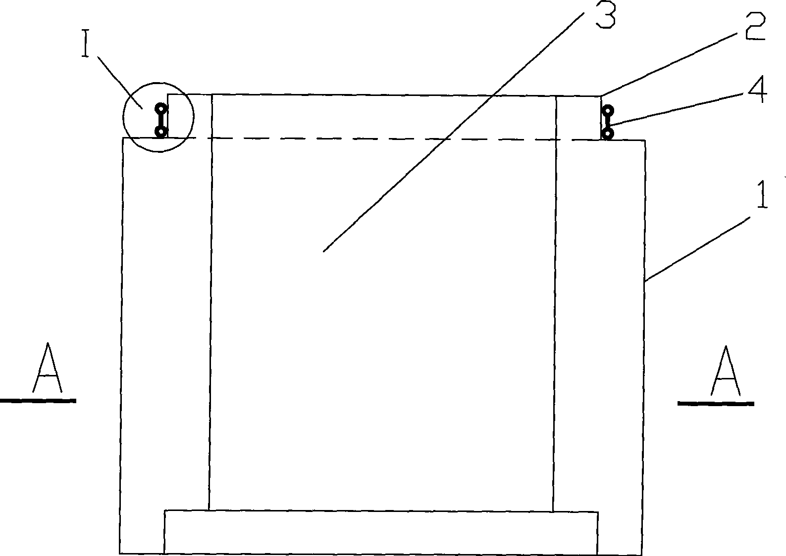
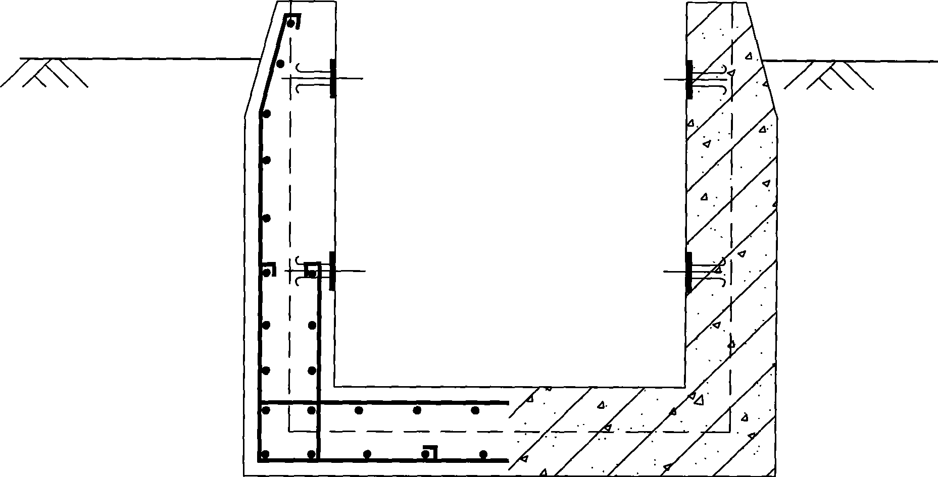
[0021] Embodiment 1, the main components of the present invention are: C30-C40 reinforced concrete or steel fiber concrete (appearance grade of fair-faced concrete) and rubber strips with double-P appearance that slightly expand when exposed to water.

[0022] Production: Customized steel molds are used, and the prefabricated site area on the construction site is factory-made on-site, moisturizing, heat-preserving and maintenance; the double-P appearance micro-expanding rubber strips are custom-processed and produced by professional manufacturers.

[0023] Installation: (1) First, on the conventional C15 plain concrete cushion, dry cement sand with a thickness of 100mm is used for leveling the assembled cable trench body after installation; (2) Use the P200 excavator standing on the site for transportation and Installation; (3) When connecting, make full use of the lap groove invented by the assembled cable trench body, install it up and down, and press the double P appearance ...


PUM


Abstract

The invention relates to a transformer substation assembly type cable trench body and a pavement method. The transformer substation assembly type cable trench body is mainly formed by connecting a plurality of sections of water-proof reinforced concrete trench bodies with U-shaped transverse cross-sections in sequence; a flange section and a groove which can be connected in tandem are respective arranged at the front and the rear ends of the trench body, a tongue-and-groove lapped back and forth is formed, and a rubber strip is installed between the trench bodies connected in tandem; the pavement method comprises the following steps: the cement bonded sand with thickness of 100 mm is paved on the conventional C15 plain concrete cushion course, and is used for the equalization of the assembly type cable trench body installed later; then the sections of the well prefabricated trench bodies are connected together through the lap-joint tongue-and-groove in sequence, and the rubber strip is underlaid at the connected point; and compared with the prior art, the invention has the advantages of reduced construction period, reduced pavement cost, improved work efficiency and labor productivity, greatly improved appearance quality and better popularization and application values.

Description

technical field [0001] The invention relates to a general substation assembled cable trench body, which belongs to the design technical field of substations and power plants. Background technique [0002] At present, the design of cable trenches for substations above 220kV is made into brickwork, plain concrete, and reinforced concrete cable trenches, etc., according to the embedding depth, load size, and groundwater level, to meet the cable laying requirements of substations and power plants. . However, with the development of my country's electric power industry, this kind of on-site cable trench body also faces the following problems: [0003] 1) The amount of masonry work on site is large and the construction time is long: taking a 220kV substation as an example, it is converted into a 1.1x0.85m cable trench body, and its total length is about 1100m. The estimated cost of the brick cable trench is 625 yuan / m 3 (According to the space inside the ditch, the same below),...

Claims


Application Information

Patent Timeline
Patent Type & Authority Applications(China)
IPC IPC(8): H02G9/02E04C2/06H02G1/06
Inventor 黄达余安春秀吴亮梅狄克徐建国童建国吴志力冯仁祥
Owner ZHEJIANG ELECTRIC POWER DESIGN INST
Learn More