
Rim angle excavation method by blasting for natural side hill

A hillside, natural technology, applied in the field of natural hillside corner blasting, can solve the problems of small local space, low efficiency, difficult to deal with, etc., and achieve the effect of increasing economic benefits

Active Publication Date: 2009-05-06
ANSTEEL GRP MINING CO LTD
View PDF0 Cites 9 Cited by
  • Summary
  • Abstract
  • Description
  • Claims
  • Application Information

AI Technical Summary

Problems solved by technology

Since the natural hillside is an irregular slope surface with different slopes, the roller cone drilling machine cannot drill holes in this part, so the part of the natural hillside will form an irregular triangular slope surface in the later stage due to no blasting, which is difficult to deal with
In the past, small-diameter rock drills were generally used to drill shallow holes in the upper part of the slope, and the blasting treatment was carried out several times. Due to the narrow local space and narrow working face, the treatment cycle was long and the efficiency was low, which seriously affected the mining operation level.

Method used


Image

  • Rim angle excavation method by blasting for natural side hill

Examples


Embodiment 1

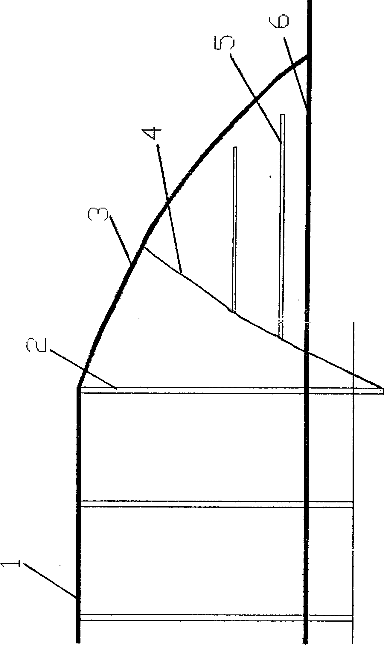
[0008] Embodiment 1: the slope of the natural hillside 3 is 30 degrees. At the junction of the natural hillside 3 and the production step 1, a row of vertical holes 2 are drilled with a roller cone drill. The hole distance of the holes is 5 meters, and the hole depth is 16 meters. ; The bottom of the hole is equipped with high-density and high-power explosives, and the millisecond differential blasting is used to break up the natural hillside. After cleaning the rocks, use a down-the-hole drill to drill two rows of horizontal holes from the broken surface 4 after blasting on the remaining irregular triangular natural hillside corners, with a hole spacing of 2 meters and a row spacing of 2 meters; the first row of holes below The height is 0.7 meters from the bottom step, and the hole depth is 8 meters; the depth of the second row of holes is 6 meters, and the rock mass at this part is blasted at one time by using the volley blasting method.

Embodiment 2

[0009] Embodiment 2: the slope of the natural hillside 3 is 45 degrees, and at the junction of the natural hillside 3 and the production step 1, a row of vertical holes 2 are drilled with a roller cone drill. The hole distance of the holes is 5 meters, and the hole depth is 15 meters ; The bottom of the hole is equipped with high-density and high-power explosives, and the millisecond differential blasting is used to break up the natural hillside. Then at the corner part of the natural hillside of the remaining irregular triangle, use the down-the-hole drill to drill two rows of horizontal holes from the broken surface 4 after the explosion, the hole spacing is 2 meters, and the row spacing is 2 meters; the height distance of the first row of holes below The bottom step is 0.5 meters, and the hole depth is 6 meters; the depth of the second row of holes is 4 meters, and the rock mass in this part is blasted at one time by using the volley blasting method.


PUM


Abstract

A method for blasting natural hillside corner belongs to the field of opencast iron ore mining and is designed aiming at the problem that a drilling machine is unable to punch, so that the formed irregular triangular sloping surfaces can not be treated when the slight pitch natural hillside is mined in an opencast way. Vertical holes are drilled at the juncture of the natural hillside and production steps, the pitch-row is reduced by 2-3 m compared with the normal operation, and the hole depth is deepen by 2-5 m compared with the normal operation. The bottom of the deep hole is provided with explosive having high density and power, and the blasting energy is utilized to blast the part close to the steps. After cleaning up, a down-the-hole drill is used for drilling 2-3 lines of horizontal holes on the crushing surface after being blasted, wherein the pitch-row is 1-2 m, and the hole depth is 6-11 m; the hillside corner is blasted by adopting the simultaneous blasting technology. The method has the characteristics of thorough blasting treatment, effective ore recovery and the like, and can be applied to the corner blasting of various slight pitch hillside surface mines.

Description

technical field [0001] The invention belongs to the field of open-pit iron ore mining, and mainly relates to a natural hillside corner blasting method applied to gently inclined natural hillsides in open-pit mining operations. Background technique [0002] In the production of open-pit mines, the blasting of open-pit mines uses roller cone drills to drill vertical deep holes on the upper part of the steps, and the drilling steps have high flatness to facilitate the drilling of roller cone drills. Since the natural hillside is an irregular slope surface with unequal slope, the roller cone drilling machine cannot drill holes in this part, so the part of the natural hillside will form an irregular triangular slope surface due to no blasting in the later stage, which is difficult to deal with. In the past, small-diameter rock drills were generally used to drill shallow holes in the upper part of the slope, and the blasting treatment was carried out several times. Due to the narr...

Claims


Application Information

Patent Timeline
Patent Type & Authority Applications(China)
IPC IPC(8): F42D3/04
Inventor 衣瑛伊之宣
Owner ANSTEEL GRP MINING CO LTD
Learn More