
Decompression valve for precipitator

A technology of dust collector and pressure relief valve, applied in the direction of safety valve, balance valve, valve device, etc., can solve the problems of reducing the service life of the dust collector, the suction and deformation of the dust collector shell, affecting the normal operation of the dust collector, etc. Normal operation, ensure the effect of deformation damage

Active Publication Date: 2012-09-26
LONGYAN WUHUAN ENVIRONMENTAL EQUIP
View PDF0 Cites 0 Cited by
  • Summary
  • Abstract
  • Description
  • Claims
  • Application Information

AI Technical Summary

Problems solved by technology

[0002] At present, one of the main means for people to control fishy air pollution is to control dust emission. The ways to control dust emission include: electrostatic precipitator, cloth bag dust removal, electric bag composite dust removal and water curtain dust removal, etc., while electrostatic precipitator and cloth bag dust removal adopt relatively Many. No matter it is electric dust removal or bag dust removal, the flue gas containing a large amount of dust is guided to the dust removal device by the induced draft fan for treatment, so as to achieve the purpose of standard discharge. However, in the process of use, due to the effect of the induced draft fan, the Negative pressure is generated inside the ventilation pipe and dust removal device. When the pipe is blocked or there is a flaw in the design and manufacturing process of the dust collector, the pressure inside the dust collector will easily cause the shell of the dust collector to suck and deform, thus affecting the normal operation of the dust collector. operation, and even reduce the service life of the dust collector.

Method used


Image

  • Decompression valve for precipitator
  • Decompression valve for precipitator

Examples


Embodiment Construction

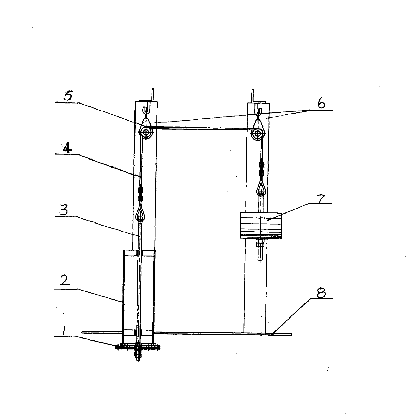
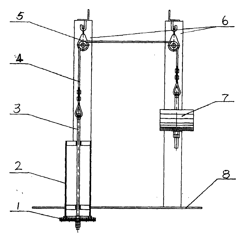
[0010] The pressure relief valve of the present invention that is used for dust remover as shown in the accompanying drawing is made up of valve plate 1, guide rod 3, valve body 2, steel wire rope 4, pulley 5, bracket 6 and counterweight 7, and valve body 2 is installed in the dust remover On the housing 8, one end of the guide rod 3 passes through the valve body 2 and is connected to the valve plate 1 placed in the housing 8, and the other end of the guide rod 3 is connected to the counterweight 7 through the steel wire rope 4; The bracket 6 is fixed in the groove of the pulley 5 on the housing 8.

[0011] During industrial manufacturing, the valve plate 1 is first connected to one end of the guide rod 3, and the other end of the guide rod 3 passes through the valve body 2 and the cover plate, and then the valve body 2 is put into the hole processed in the dust collector housing 8. In the inner part, the valve plate 1 is placed in the dust collector housing 8, and the valve b...


PUM


Abstract

The invention discloses a pressure release valve for dust removers, which aims to solve the problems that a shell of the prior dust remover sinks down, deforms and the like. The pressure release valve consists of a valve plate (1), a guide rod (3), a valve body (2), a steel wire rope (4), a pulley (5), a bracket (6) and a counterweight block (7), wherein the valve body (2) is arranged on a dust remover shell (8); one end of the guide rod (3) passes through the valve body (2) and is connected with the valve plate (1) arranged in the shell (8); and the other end of the guide rod (3) is connected with the counterweight block (7) through the steel wire rope (4). Therefore, the pressure release valve has the advantages that the valve is simple to machine, and can effectively prevent the dust remover shell from sinking down, deforming and the like.

Description

[0001] Technical Field The present invention relates to a pressure relief valve for a dust collector. Background technique [0002] At present, one of the main means for people to control fishy air pollution is to control dust emission. The ways to control dust emission include: electrostatic precipitator, cloth bag dust removal, electric bag composite dust removal and water curtain dust removal, etc., while electrostatic precipitator and cloth bag dust removal adopt relatively Many. No matter it is electric dust removal or bag dust removal, the flue gas containing a large amount of dust is guided to the dust removal device by the induced draft fan for treatment, so as to achieve the purpose of standard discharge. However, in the process of use, due to the effect of the induced draft fan, the Negative pressure is generated inside the ventilation pipe and dust removal device. When the pipe is blocked or there is a flaw in the design and manufacturing process of the dust collecto...

Claims


Application Information

Patent Timeline
Patent Type & Authority Patents(China)
IPC IPC(8): F16K17/12F16K17/164H05K5/00
Inventor 温荣胜傅长辉林莹
Owner LONGYAN WUHUAN ENVIRONMENTAL EQUIP
Learn More