
Anti-fire test device of restrained beam

A technology for testing devices and restraining beams, which is applied in measuring devices, testing of machine/structural components, material inspection products, etc., and can solve problems such as fire resistance performance tests of beams that cannot be restrained

Inactive Publication Date: 2009-04-22
HARBIN INST OF TECH
View PDF0 Cites 16 Cited by
  • Summary
  • Abstract
  • Description
  • Claims
  • Application Information

AI Technical Summary

Problems solved by technology

[0003] The purpose of the present invention is to provide a fire resistance test device for restrained beams in order to solve the problem that existing test devices cannot test the fire resistance performance of restrained beams

Method used


Image

  • Anti-fire test device of restrained beam
  • Anti-fire test device of restrained beam
  • Anti-fire test device of restrained beam

Examples


specific Embodiment approach 1

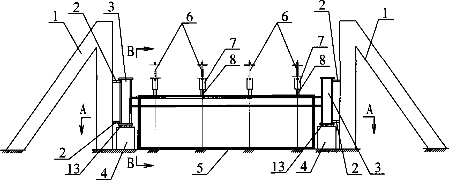
[0007] Specific implementation mode one: combine figure 1 , figure 2 , image 3 and Figure 5 Describe this embodiment, this embodiment includes two reaction force frames 1, four tension and pressure sensors 2, two restraining steel columns 3, two specimen supports 4, furnace body 5, at least one vertical loading device 6, At least one jack 7, at least one load cell 8, oil pump 9, oil tank 10, blower fan 11, at least two thermocouples 12, at least four rollers 13 and at least one nozzle 14, two specimen supports 4 are arranged longitudinally on On the ground, two reaction frames 1 are arranged on the outer ground of the two test piece supports 4 facing each other, and at least two rollers 13 are arranged on the upper end surface of each test piece support 4, and two restraining steel columns 3 are respectively vertically arranged on the rollers 13 on the two test piece supports 4, every two tension and pressure sensors 2 are arranged up and down between the reaction force ...

specific Embodiment approach 2

[0008] Specific implementation mode two: combination Figure 6 Describe this embodiment, the furnace body wall around the furnace body 5 of this embodiment is formed by refractory bricks, the furnace body wall around the furnace body 5 is formed by common red bricks, and the furnace body wall around the furnace body 5 Refractory fibers are filled between the outer wall and the furnace body 5, and the bottom of the furnace body 5 is made of two layers of refractory bricks. This design makes the furnace body 5 have a good thermal insulation effect, simple structure and low cost.

specific Embodiment approach 3

[0009] Specific implementation mode three: combination figure 2 and Figure 5 Describe this embodiment, the furnace body wall of the flue 5-2 side of the furnace body 5 of this embodiment is provided with the observation hole 5-3. The observation hole 5-3 is convenient for observing the combustion situation in the furnace body 5 and the changes of the test components during the test process. The observation hole 5-3 can also be used to connect some data measurement wires required in the test to the outside of the furnace body 5 data acquisition or processing device.


PUM


Abstract

The invention relates to a fire-resistance testing device, in particular to a fire-resistance testing device used for a restrained beam. The invention aims at solving the problem that the existing testing device can not test the fire-resistance performance of the restrained beam. Two sample supporters are longitudinally arranged on the ground surface; two reaction frames are positively arranged on the ground surface at the external side of the two sample supporters; a restraining steel column is vertically arranged on a rolling shaft; a tension-compression sensor is arranged between the reaction frame and the restraining steel column; a furnace body is arranged on the ground surface between the two sample supporters; two anchor rods on a vertical-loading device are transversely arranged at two sides of the furnace body; a jack and a weighing sensor are respectively arranged at the upper part and the lower part of the lower surface of a reaction steel beam; a nozzle is arranged at a sprout; an oil pump is connected with the nozzle; the oil pump is connected with an oil tank; a fan is communicated with the sprout; the furnace body is provided with a flue; the thermocouple is arranged on the furnace body wall; in the invention, the testing device is provided for the fire-resistance test of the restrained beam, and the test requirements required by the test such as temperature increment, boundary constrains, reaction measurement, loading, and the like are met.

Description

technical field [0001] The invention relates to a fire resistance test device. Background technique [0002] Fire is a hazard caused by uncontrolled burning, and it is also a disaster faced by mankind. It can ruthlessly take away the precious lives of many people, and can reduce the wealth created by mankind for many years to ashes in an instant. Fires can be mainly divided into building fires, forest fires, industrial and mining fires, and transportation fires. Among them, building fires are the most direct and serious harm to people, because various types of buildings are the main places for people's life and production activities, and they are also places where property is highly concentrated. One of the most important issues that should be considered when dealing with The beam is the main horizontal load-bearing component of the building. Its main task is to bear the load from the floor and transfer the load to the column at the same time. In actual engineering, as a ...

Claims


Application Information

Patent Timeline
Patent Type & Authority Applications(China)
IPC IPC(8): G01N33/38G01M19/00G01M99/00
Inventor 董毓利杨志年吕俊利王勇张大山
Owner HARBIN INST OF TECH
Learn More