
Equipment for recognizing composite material quality and interface by electric vortex flow

A composite material and eddy current technology, applied in the direction of material magnetic variable, etc., can solve the problem that the eddy current detector cannot realize the control of the detection depth, cannot meet the measurement requirements of thin-layer materials with different thicknesses, and does not have the function of identifying and locating the interface of composite materials, etc. problem, to achieve the effect of simple structure, strong anti-interference ability and high sensitivity

Inactive Publication Date: 2009-04-22
SHANGHAI JIAO TONG UNIV
View PDF1 Cites 7 Cited by
  • Summary
  • Abstract
  • Description
  • Claims
  • Application Information

AI Technical Summary

Problems solved by technology

[0004] After searching the literature of the prior art, it is found that the Chinese patent application number is 200620077665.3, the patent publication number is CN201041561Y, and the patent name is "A New Type of Eddy Current Detector". A device for detecting materials, the patent uses a suppression circuit to suppress the noise interference in the detection, but its disadvantage is that it can only suppress the noise below a certain level, and in the complex online detection environment, the signal Noise in the same order of magnitude or greater than the signal strength, this suppression circuit cannot eliminate such noise interference in principle
In addition, this eddy current detector cannot control its detection depth, and cannot meet the measurement requirements for thin-layer materials with different thicknesses; moreover, this eddy current detector does not have the function of identifying and locating the interface of composite materials

Method used


Image

  • Equipment for recognizing composite material quality and interface by electric vortex flow
  • Equipment for recognizing composite material quality and interface by electric vortex flow

Examples


Embodiment Construction

[0034] The embodiments of the present invention are described in detail below in conjunction with the accompanying drawings: this embodiment is implemented on the premise of the technical solution of the present invention, and detailed implementation methods and specific operating procedures are provided, but the protection scope of the present invention is not limited to the following the described embodiment.

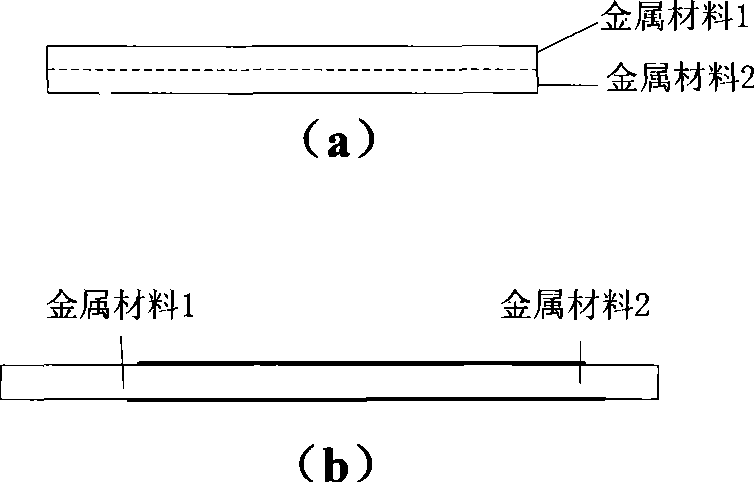
[0035] Such as figure 1 As shown, it is the detection object of this embodiment—the electrical component material. This type of composite material is made of two different non-ferromagnetic metal thin layer materials. Composite material, (b) is a composite material in which two materials are spliced ​​back and forth.

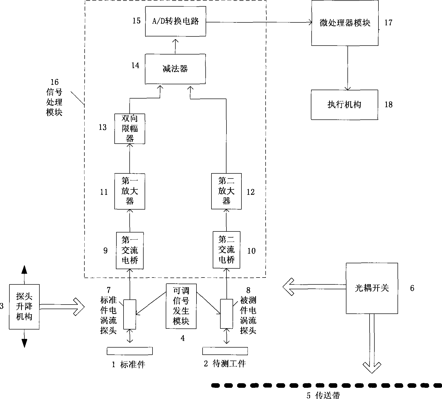
[0036] Such as figure 2 As shown, this embodiment includes: an adjustable signal generating module 4, an optocoupler switch 6, a standard eddy current probe 7, a DUT eddy current probe 8, a probe lifting mechanism 3, a signal processing module 16, an...


PUM


Abstract

The invention provides an eddy current recognition composite material and equipment on the interface thereof, belonging to the technical field of metal material recognition. An adjustable signal generation module generates electric signals with frequency being adjustable continuously; furthermore, the signals are respectively transmitted to the eddy current probe of a standard part and the eddy current probe of a part to be measured, and the eddy current probe of the standard part and the eddy current probe of the part to be measured are connected with a probe lifting mechanism; two probes convert the input electric signals into magnetic signals, emits the magnetic signals to the surface of the composite lamellar material and receives the returned signals; a signal processing module respectively receives the signals output by the two probes; a subsequent execution mechanism is controlled by two signals; an optical-coupling switch detects the position of the workpiece; a micro-processing module controls the adjustable signal generation module to send signals to the eddy current probe of the standard part and the eddy current probe of the part to be measured and controls the execution mechanism to start operations. The composite material and the equipment have recognition function for the composite lamellar material and can position for the recognition of the different material interfaces of the composite material; the operation is simple and the application is wide.

Description

technical field [0001] The invention relates to a device in the technical field of detection, in particular to a device for eddy current identification of a composite material material and its interface. Background technique [0002] With the advancement of my country's industrialization process, the level of industrial automation will continue to improve. At present, most of the domestic electrical component manufacturing and metal fittings processing industries are still processed by manual material selection and feeding. This work process is simple and tedious, and with the significant increase in labor costs, the use of online automatic identification, sorting and feeding will become an inevitable trend. At present, the material identification methods mainly include: specific gravity identification, photothermal identification, color identification, electromagnetic identification, eddy current identification and other methods. Various identification methods have their ...

Claims


Application Information

Patent Timeline
IPC IPC(8): G01N27/72
Inventor 黄峰一吉小军宫延伟裘揆
Owner SHANGHAI JIAO TONG UNIV
Learn More