
Hydraulic claw bucket of slotting machine

A hydraulic grab and slotting machine technology, which is applied in the direction of earth mover/shovel, construction, etc., can solve the problems of increasing the load capacity of the crane, increasing the cost of the crane, etc., to increase the weight, increase the excavation depth, and light weight Effect

Inactive Publication Date: 2009-04-22
丁明明
View PDF0 Cites 2 Cited by
  • Summary
  • Abstract
  • Description
  • Claims
  • Application Information

AI Technical Summary

Problems solved by technology

If the weight of the hydraulic grab is simply increased, the load capacity of the crane will be increased, which will increase the cost of the crane

Method used


Image

  • Hydraulic claw bucket of slotting machine
  • Hydraulic claw bucket of slotting machine
  • Hydraulic claw bucket of slotting machine

Examples


Embodiment Construction

[0014] best practice

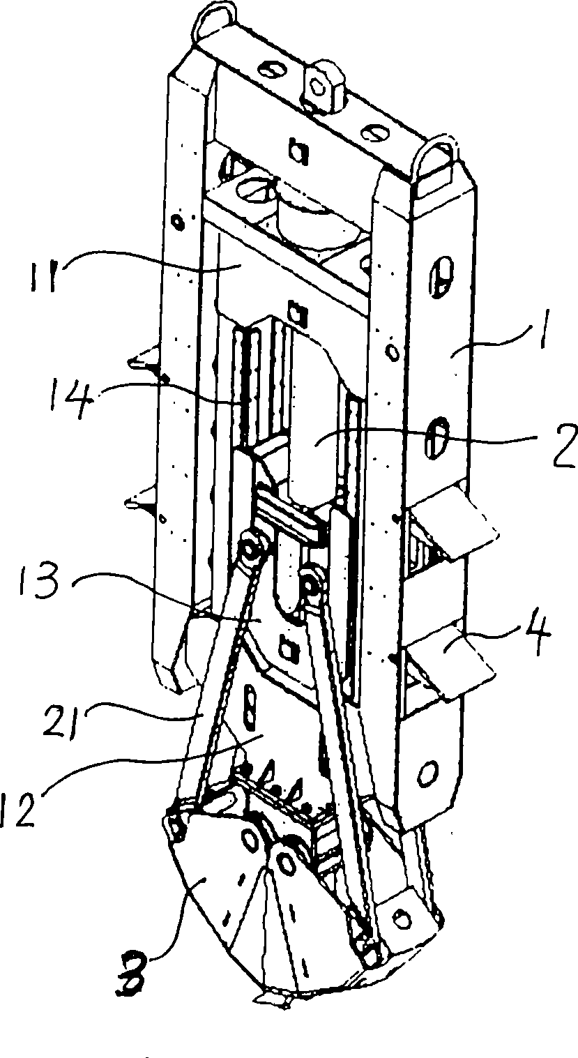
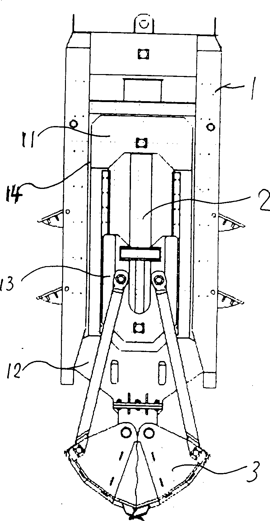
[0015] The present invention is an improvement to the hydraulic grab bucket of the existing slotting machine. One of the structures of the hydraulic grab bucket of the existing slotting machine is composed of a fuselage 1, a hydraulic device 2 and a grab bucket 3. The fuselage 1 is an upright giant frame structure, and its upper part is provided with a fixing seat 11 of a hydraulic device 2 . The top end of the piston rod 21 of the hydraulic device 2 is fixedly connected with the moving block 13 , and the moving block 13 is installed in the guide grooves 14 on both sides of the fuselage 1 . The lower end of the fuselage 1 is provided with a fixing seat 12 of the grab bucket 3 . The grab bucket 3 is affixed to the lower end of the fuselage 1 through the fixing seat 12 . The moving block 13 is movably connected with the grab bucket 3 through a connecting rod 15 .

[0016] The present invention requires that the hydraulic grab can also have other structu...


PUM


Abstract

The invention relates to an underground continuous wall grooving machine, in particular to a hydraulic crab bucket of the grooving machine. The aim of the invention is to solve a problem of generating a hollow cutting phenomenon due to the upward floating of a machine body when the hydraulic crab bucket grabs and closes, and provide the hydraulic crab bucket provided with power assisting devices. The structure of the grooving machine consists of the machine body, a hydraulic device and a crab bucket, wherein two sides of the machine body are at least provided with a power assisting device respectively. The grooving machine has the advantages that when an excavation project is in an underground deep trench and comes across an underground hard soil layer, the power assisting devices of the grooving machine can be started. When the power assisting devices at the two sides of the machine body of the hydraulic crab bucket are opened, the whole machine body can be blocked in the trench, and then, when the crab bucket downwards excavates a hard soil layer, under the action of the power assisting devices, the upward floating of the machine body can be avoided. The key points are that the grooving machine has low cost and light weight, is arranged on the hydraulic crab bucket, and can achieve the effect of increasing the weight without increasing the load capacity of a hoister. At the same time, the excavating depth can be increased.

Description

technical field [0001] The invention relates to an underground continuous wall grooving machine, in particular to a hydraulic grab bucket of the grooving machine. Background technique [0002] With the rapid development of my country's economy, the urban rail transit network is becoming more and more developed. For the construction of subway stations, transfer stations for two or even three subway lines have appeared, and the transfer stations of the subway have been built deeper and deeper, and the depth from the ground has reached more than 42 meters. In addition, it is very difficult to excavate the hard soil layer deep underground. For example: 30 meters underground in Shanghai, there is a layer of hard soil, commonly known as iron plate sand, with a thickness of about 5 to 8 meters. It is difficult for the hydraulic grab bucket of an ordinary diaphragm wall forming machine to reach a depth of 42 meters underground, let alone excavate hard soil layers. The main reason...

Claims


Application Information

Patent Timeline
Patent Type & Authority Applications(China)
IPC IPC(8): E02F5/02
Inventor 丁明明
Owner 丁明明
Learn More