
Electric power plant circulating water rock plug type intake and construction method

A water intake and circulating water technology, which is applied in water conservancy projects, marine engineering, hydropower generation, etc., can solve the problems such as the outage of the first and second phase units, affecting the operation efficiency of the circulating water system, and the hidden danger of blasting impact force.

Inactive Publication Date: 2009-04-22
ZHEJIANG ELECTRIC POWER DESIGN INST
View PDF0 Cites 11 Cited by
  • Summary
  • Abstract
  • Description
  • Claims
  • Application Information

AI Technical Summary

Problems solved by technology

However, due to the large amount of blasting, the impact force of the blasting poses a great safety hazard to the circulating pump facilities of the first and second phases of Wenzhou Power Plant, which is running nearby. If it is serious, it will cause a major accident of the shutdown of the first and second phases
Since the diversion water of the open channel is a surface flow, affected by the backflow of the drainage, the water intake temperature is higher than that of the diversion tunnel for deep water intake, which affects the operating efficiency of the circulating water system, thereby affecting the power generation efficiency of the power plant
In addition, since the open channel is open and directly communicates with the outside water, it is often blocked by a large number of river drifts during the annual flood season.

Method used


Image

  • Electric power plant circulating water rock plug type intake and construction method

Examples


Embodiment Construction

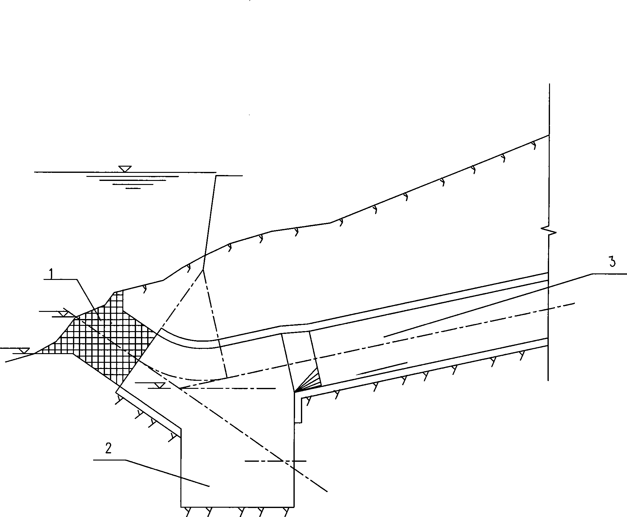
[0013] The present invention will be described in detail below in conjunction with accompanying drawing and example: figure 1 As shown, the rock plug type water intake of the present invention is arranged near the deep pool, and mainly consists of a rock plug 1, a ballast collection pit 2 and a water diversion tunnel 3 behind. The water diversion tunnel 3 is arranged in the mountain body and is inclined downward near the axis of the inlet section so that the axis of the rock plug water intake maintains an upward inclination of 35° to 60°. A sinking type ballast collection pit 2 is built between the diversion tunnel 3 and the rock plug 1 .

[0014] The cross section of the diversion tunnel 3 and the rock plug 1 is circular or quasi-circular or square or rectangular, figure 1 Shown is circular; the rock plug described has a thickness-to-diameter ratio of 1.13.

[0015] The construction method of the present invention is: the excavation construction of the water diversion tunne...


PUM


Abstract

The invention provides a rock-plug type water intake for the circulating water of power plants, as well as a construction method thereof. The rock-plug type water intake is arranged near a deep pool and mainly comprises a rock plug, a ballast collection pit and a derivation tunnel behind the ballast collection pit, wherein the derivation tunnel is arranged in a mountain body; an axis close to an inlet segment declines so as to keep the axis of the rock-plug type water intake at an upward inclination angle between 35 and 60 degrees; the outlet end of the derivation tunnel is directly connected with an inflow forebay of a circulating pump room; the sinking-type ballast collection pit is built between the derivation tunnel and the rock plug; the cross sections of the derivation tunnel and the rock plug are round, similarly round, square or rectangular; and the thickness-diameter ratio of the rock plug is between 1.13 and 1.50. The construction method comprises the following steps: the excavation construction of the derivation tunnel and the ballast collection pit is performed according to a new Austrian method; whether to line or not is determined according to the conditions of bedrock; the rock plug is blasted by use of a presplitting and millisecond time interval method; and once the rock plug is blasted, all ballast of the rock plug enters the prearranged ballast collection pit under the action of external water pressure. The construction method has the advantages of reducing project investment, shortening construction period, improving the operation efficiency of a circulating water system, and the like.

Description

technical field [0001] The invention relates to a seaside power plant, including a water intake for circulating water in the rock foundation area of ​​coal, fuel oil, gas, nuclear power, etc. and a construction method, and belongs to the technical field of power plants. Background technique [0002] Coastal power plants generally adopt a once-through circulating water system. In order to ensure its reliable and economical operation, according to the requirements of the "Technical Regulations for Design of Thermal Power Plants", the intake and drainage must be arranged according to the principle of "deep intake and shallow drainage", namely: water intake The setting of the bottom elevation must be able to meet the seawater flow requirements of the minimum tide level with a guaranteed rate of 95% to 97%. [0003] In order to save investment, the water intake construction crops of the Binhai Power Plant are often arranged on the seaside hills with good geological conditions in ...

Claims


Application Information

Patent Timeline
IPC IPC(8): E02B3/00E02B9/04
CPCY02E10/22Y02E10/20
Inventor 吴建国张浙杭童建国李琪张根土包连陈宋浩君刘显群
Owner ZHEJIANG ELECTRIC POWER DESIGN INST
Learn More