Solar automobile
A technology of solar energy and solar panels, applied in the field of automobiles, can solve problems such as the size of the area and the volume limit of the vehicle, and achieve the effects of reducing the area, improving the utilization rate, and reducing the resistance
- Summary
- Abstract
- Description
- Claims
- Application Information
AI Technical Summary
Problems solved by technology
Method used
Image
Examples
no. 1 example
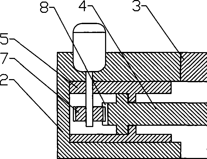
[0020] The first embodiment: as figure 1 As shown, the solar car includes a car body 1, a support 2 fixedly installed on the top of the car body 1, a fixed solar panel 3 installed on the support 2, a slide rail 5 is installed on the support 2, and 2 A movable solar panel 4, and the movable solar panel 4 is connected with the drive motor 6 through a transmission mechanism.
[0021] Such as figure 2 and image 3 As shown, the transmission mechanism includes a drive gear 7 fixedly installed on the motor shaft of the drive motor 6, a rack 8 is fixedly installed on one side of the movable solar panel 4 located in the slide rail 5, and the drive gear 7 meshes with the rack 8 Under the action of the drive motor 6, the movable solar panel 4 can be stretched out or retracted from both sides of the car body 1, that is, when the drive motor 6 starts, the drive gear 7 and the rack 8 drive the movable solar panel 4 to extend to both sides. To achieve the purpose of increasing the solar...
no. 2 example
[0023] The second embodiment: as Figure 5 and Figure 6 As shown, the basic structure of this embodiment is the same as that of the first embodiment, the difference is that the slide rail 5 on the support 2 has two layers, each layer is provided with two movable solar panels 4, and the motor of the driving motor 6 2 drive gears 7 are fixedly installed on the shaft, and the drive gear 7 corresponds to each layer of movable solar panel 4, and the moving direction of the rack 8 of the upper movable solar panel 4 is perpendicular to the moving direction of the rack 8 of the lower movable solar panel 4. The solar panels 4 are just 4 pieces, which can extend respectively from the left, right and front and back of the car body 1, thereby increasing the area of the solar panels to a greater extent.
no. 3 example
[0024] The third embodiment: as Figure 7 and Figure 8 As shown, the basic structure of this embodiment is the same as that of the first embodiment, the difference is that the transmission mechanism includes a commutator 9 installed on the drive motor 6, and screw rods 10 are respectively installed on both sides of the commutator 9, The screw rod 10 is located below the movable solar panel 4, and the screw rod 10 is provided with a slide block 11. The slide block 11 is fixedly connected with the bottom surface of the movable solar panel 4, and the extension and retraction of the movable solar panel 4 are realized by rotating the screw rod 10, and the screw rod 10 10 and the slider 11 can be used as a support for the movable solar panel 4 to fix and support the movable solar panel 4 .
[0025] Certainly, the driving motor 6 described above is controlled by the control circuit, and the structure and principle of the control circuit are known technologies, and will not be repea...
PUM
 Abstract
Description
Claims
Application Information
 - R&D
- Intellectual Property
- Life Sciences
- Materials
- Tech Scout
- Unparalleled Data Quality
- Higher Quality Content
- 60% Fewer Hallucinations
Browse by: Latest US Patents, China's latest patents, Technical Efficacy Thesaurus, Application Domain, Technology Topic, Popular Technical Reports.
© 2025 PatSnap. All rights reserved.Legal|Privacy policy|Modern Slavery Act Transparency Statement|Sitemap|About US| Contact US: help@patsnap.com


