Laser welding method, laser welding device, and production method of blower-use impeller

A technology of laser welding and laser irradiation, which is applied in the components, applications, and mechanical equipment of pumping devices for elastic fluids, and can solve problems such as insufficient welding, defective products, and resin burning.

Active Publication Date: 2009-04-15
DAIKIN IND LTD
View PDF1 Cites 6 Cited by
  • Summary
  • Abstract
  • Description
  • Claims
  • Application Information

AI Technical Summary

Problems solved by technology

[0005] However, as described above, when the blade is welded to the end plate or end ring while moving the irradiation position of the laser, if dust or metal powder, etc. Dust or metal powder, etc. will ignite due to laser irradiation, causing the resin at the irradiated position of the fire to burn, and due to the movement of the laser irradiated position, there is a possibility that the laser will burn from the irradiated position where the dust or metal powder, etc. Burning of the resin is continuously generated on the irradiation path of the
[0006] In this way, when the dust or metal powder is ignited, there will be traces of burning on the irradiation path of the laser from the irradiated position where the dust or metal powder ignites in the overlapped part, and defective products will appear.
In particular, since the material constituting the end plate and the end ring is made of transparent or translucent resin material or the like, which has a light transmittance higher than that of the material constituting the blades, such burning traces are very obvious, and it is not preferred
In addition, the occurrence of burning of the resin means that the energy from the laser is consumed during the burning of the resin, so the welding of the resin parts may be insufficient in the part where the burning marks remain.

Method used


Image

  • Laser welding method, laser welding device, and production method of blower-use impeller
  • Laser welding method, laser welding device, and production method of blower-use impeller
  • Laser welding method, laser welding device, and production method of blower-use impeller

Examples


Embodiment

[0046] Next, an embodiment in which the above-mentioned laser welding method and laser welding apparatus are used in a method of manufacturing an impeller for a blower will be described with reference to the drawings.

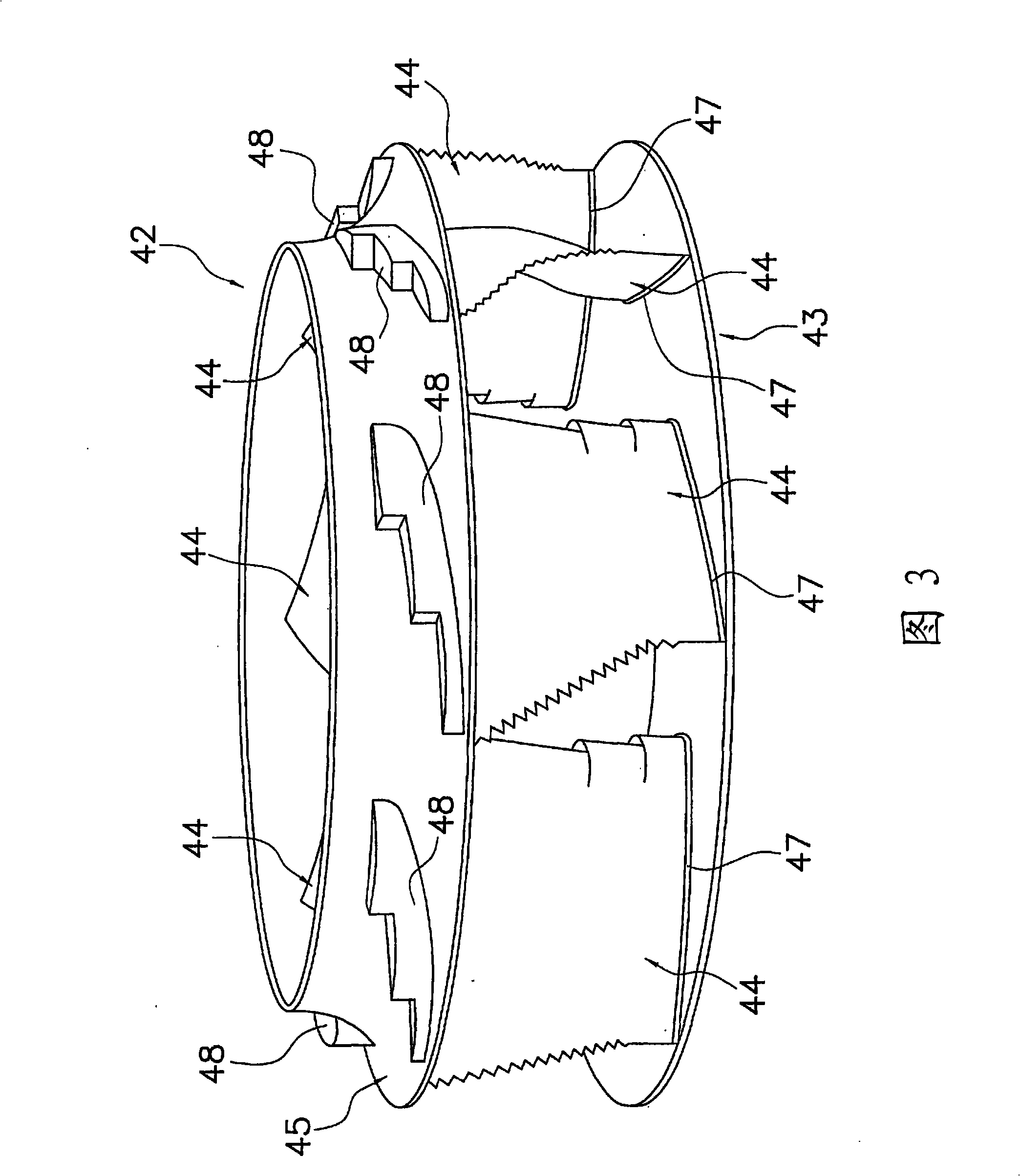
[0047] (1) The structure of the impeller for the blower

[0048] Figure 3~ Figure 5 The fan impeller 42 of this embodiment is shown. The blower impeller 42 is an impeller for a turbo fan, and mainly includes: a disc-shaped end plate 43 as a blade supporting rotating body; ) the blade 44 ; and an annular end ring 45 serving as a blade supporting rotating body, which is disposed so as to hold the plurality of blades 44 between the end plate 43 . Here, let O be the center of rotation of the impeller 42 for a blower, and let R be the rotation direction of the impeller 42 for a blower. 3 is an external perspective view of the impeller 42 for a blower. Figure 4 It is the figure which looked at the impeller 42 for blowers from the end ring 45 side. Figure 5 is...


PUM


Abstract

A laser welding method for performing laser irradiation while moving an irradiation position, wherein the possibility of a combustion trace remaining on a laser beam irradiation path is minimized even dust, metal powder or the like deposited on the overlapped portion of resin members is ignited by laser irradiation. A laser welding method, wherein overlapped portion (13) is formed by laying a transmitting resin member (11) over an absorbing resin member (12) lower in light transmittance than the transmitting resin member (11), the overlapped portion (13) is then irradiated with laser from the transmitting resin member (11) side while the irradiation position is moved, and nonflammable gas is sprayed onto the irradiation position from the transmitting resin member (11) side in association with a moving laser beam irradiation position.

Description

technical field [0001] The present invention relates to a laser welding method, a laser welding device, and a method of manufacturing an impeller for a blower, and particularly to a laser welding method for welding resin parts while moving a laser irradiation position, and a laser welding device used in the laser welding method And a method of manufacturing an impeller for a blower using the laser welding method. Background technique [0002] Conventionally, air blowers such as turbofans and Sirocco fans have been used in ventilators, air conditioners, and air cleaners. As shown in Patent Document 1, the impeller for blowers constituting such a blower has a resin end plate, It rotates around the rotating shaft by a driving mechanism such as a motor; a plurality of resin-made blades, which have a hollow space formed inside; and a resin-made end ring, which is arranged to hold the blades between the end plates, The impeller for blower is produced by performing laser welding b...

Claims


Application Information

Patent Timeline
IPC IPC(8): B29C65/16F04D29/28B29L31/08
CPCB29C66/001B29C66/43B29C66/54B29C65/1635B29C65/1654B29C66/1122F04D29/30B29C65/1658F04D29/023B29L2031/08B29C66/00141B29C65/10F04D29/282B29C66/543B29C66/5344B29C66/5346B29C66/124B29C66/12469B29C66/836B29C66/002B29K2995/0025B29K2995/0027F05D2300/44F05D2230/234
Inventor 西野久则
Owner DAIKIN IND LTD
Why Eureka
Try Eureka