Field emission electrode, a manufacturing method thereof, and a manufacturing apparatus thereof
A technology for emitting electrodes and emitting electrons, which is applied in the manufacture of electrode systems, cold cathodes, discharge tubes/lamps, etc., and can solve problems such as deviations in electron emission characteristics of electron emission films
- Summary
- Abstract
- Description
- Claims
- Application Information
AI Technical Summary
Problems solved by technology
Method used
Image

Examples
no. 1 example
[0132] Next, in order to see the results of performing aging using a humidified state, aging was performed by performing humidification treatment, and a case where baking treatment was performed was compared with a case where humidification treatment was omitted and aging treatment and baking treatment were performed under the same conditions .
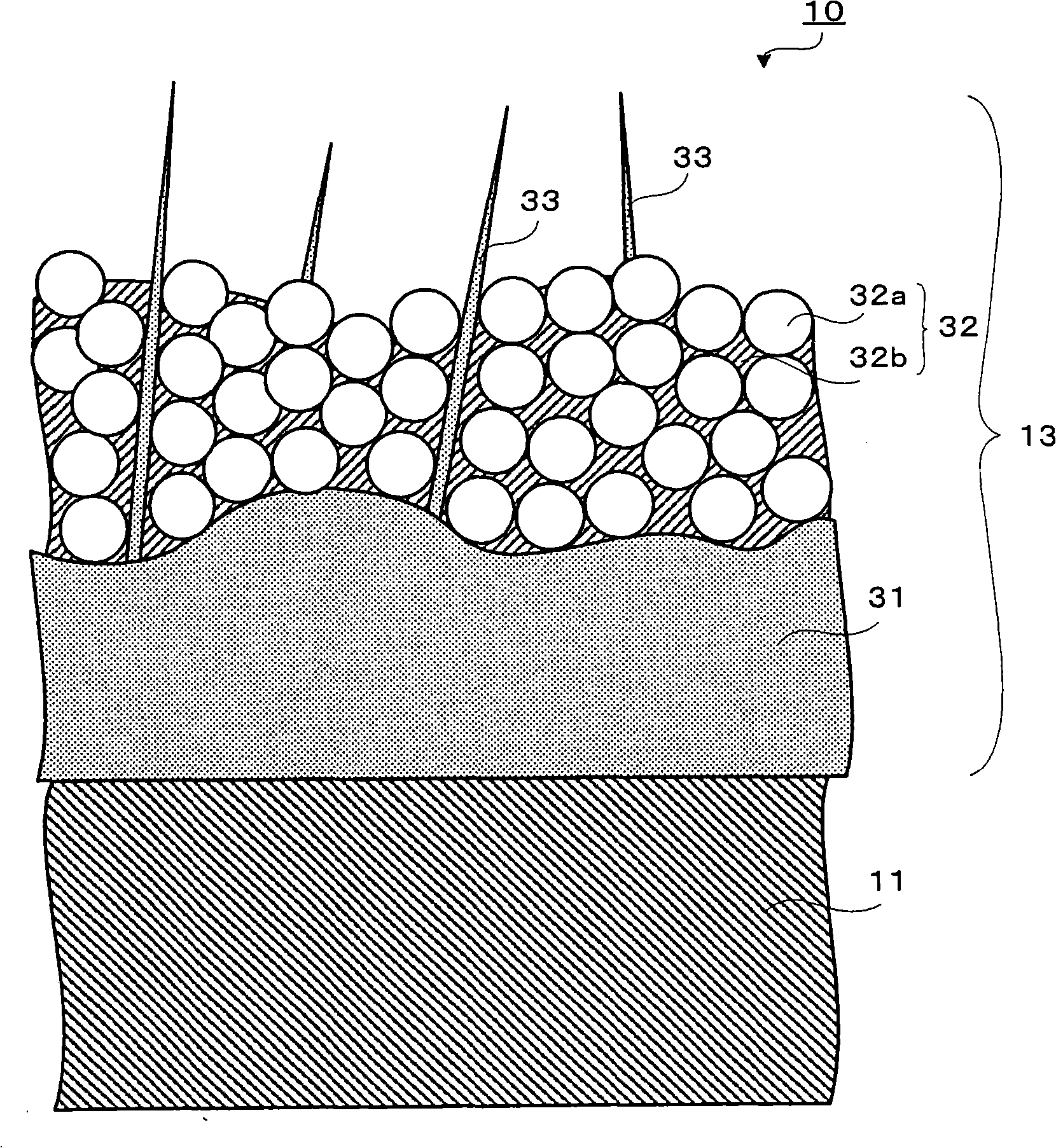
[0133] First, an electron emission film 13 is formed on a substrate by a CVD apparatus under the above conditions, and a field emission electrode is formed. Next, the electron emission film 13 of the field emission electrode formed in this way is subjected to a humidification treatment. Specifically, in a high-humidity environment, the humidification process is performed by exposing to, for example, a room temperature of 25 degrees Celsius and a humidity of 100% for about one minute. Then dry on 50% humidity for about ten minutes.
[0134] Next, the humidified electron emission film having a size of 30 mm x 30 mm was paired using th...
no. 2 example
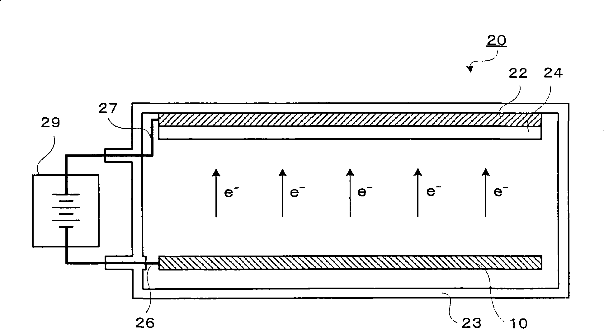
[0149] Next, the following two cases were compared: a case where humidification treatment was performed using a copper sheet (which is a water repellent material) as an anode, aging treatment was performed, and baking treatment was performed; ) is a case where the processing equipment as the anode is subjected to aging while performing the humidification treatment as in the first embodiment, and then performing the baking treatment. Effect of the case on the anode of the field emission electrode. 24 to 33 of the first embodiment show the data of performing aging and then performing baking treatment for a treatment apparatus using a glass plate covered with a fluorescent substance (ZnO:Zn) on ITO as an anode in addition to humidification treatment . In the second embodiment, only data are shown for the case of using a copper sheet instead of a phosphor (ZnO:Zn)-coated glass plate on ITO as an anode.
[0150] First, as in the first embodiment, an electron emission film was for...
no. 3 example
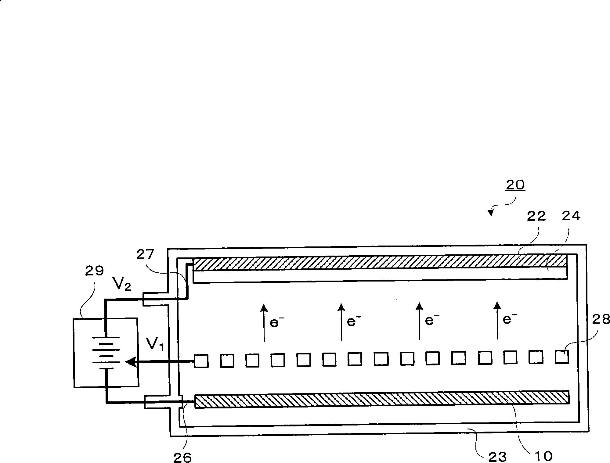
[0162] Next, in order to see the effect of applying a pulse voltage, the case where aging by applying a pulse voltage was performed in a wet state was compared with the case where aging by applying a DC fixed voltage instead of a pulse voltage was performed in a wet state.
[0163] First, as in the first embodiment, an electron emission film was formed on a substrate under the above conditions by a plasma CVD apparatus, and a field emission electrode was prepared. Next, the electron emission film of the field emission electrode formed in this way is subjected to a humidification treatment. Specifically, the humidification treatment is performed by exposing to a room temperature of, for example, 25 degrees Celsius and a humidity of 100% for about one minute in a high-humidity environment. Drying is then carried out at 50% humidity for approximately 10 minutes.
[0164] Next, burn-in is performed on a processing apparatus having substantially the same configuration as that of t...
PUM
 Abstract
Description
Claims
Application Information
 - R&D
- Intellectual Property
- Life Sciences
- Materials
- Tech Scout
- Unparalleled Data Quality
- Higher Quality Content
- 60% Fewer Hallucinations
Browse by: Latest US Patents, China's latest patents, Technical Efficacy Thesaurus, Application Domain, Technology Topic, Popular Technical Reports.
© 2025 PatSnap. All rights reserved.Legal|Privacy policy|Modern Slavery Act Transparency Statement|Sitemap|About US| Contact US: help@patsnap.com