Grounding electrode insulation screen structure and its setting method

A grounding electrode, insulation shielding technology, applied in the direction of connecting parts to protect grounding/shielding devices, magnetic field/electric field shielding, electrical components, etc., can solve problems such as occupation, increased land acquisition costs, and large land area

Inactive Publication Date: 2009-04-08
STATE GRID CORP OF CHINA
View PDF0 Cites 2 Cited by
  • Summary
  • Abstract
  • Description
  • Claims
  • Application Information

AI Technical Summary

Problems solved by technology

However, at present, many DC grounding electrode sites are farmland, and the soil needs to be returned to local residents for cultivation after the grounding electrodes are buried.
If the entire area of ​​land is to be occupied, the cost of land acquisition will be greatly increased, which is not economically cost-effective
[0012] 2. Increase the size of the ground electrode
However, increasing the size of the grounding electrode also means that a larger land area needs to be occupied, which not only needs to increase the cost of land acquisition, but also in some cases, due to the limitation of the actual geological conditions, the available land area is limited, and the size of the grounding electrode cannot be increased.
[0013] 3. Increase the buried depth of the ground electrode
Increasing the buried depth can reduce the maximum step voltage, but it also means that the amount of earthwork that needs to be excavated increases, and the construction cost increases
Moreover, the research and experimental data show that when the burial depth is deeper, the amount of soil that needs to be excavated increases in series, and increasing the burial depth reduces the step voltage of the ground electrode more than increasing the size of the ground electrode, etc. less obvious method
[0014] Therefore, the current method requires a substantial increase in construction costs or increases in land acquisition costs to reduce the step voltage of the ground electrode.

Method used


Image

  • Grounding electrode insulation screen structure and its setting method
  • Grounding electrode insulation screen structure and its setting method
  • Grounding electrode insulation screen structure and its setting method

Examples


Embodiment Construction

[0032] Exemplary embodiments of the present invention will be specifically described below with reference to the accompanying drawings.

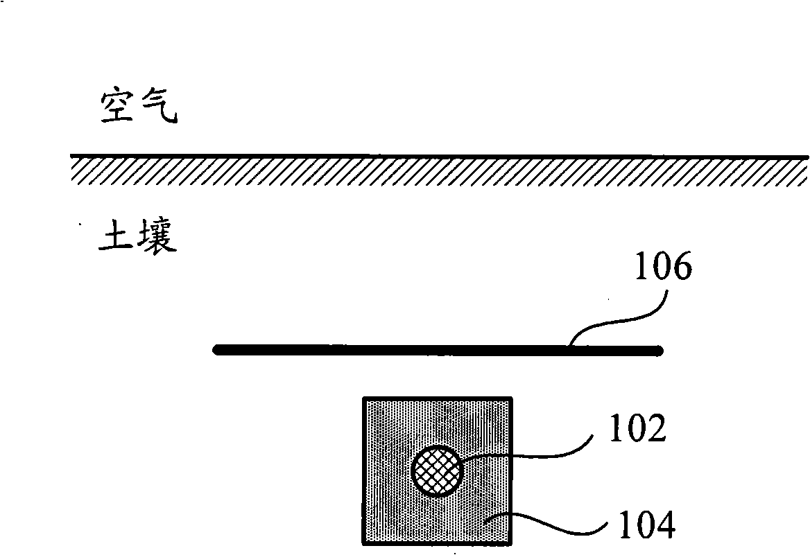
[0033] The purpose of the present invention is to overcome the deficiencies of the prior art and propose a method for reducing the maximum step voltage of the DC grounding electrode without increasing the floor area of ​​the grounding electrode and without greatly increasing the construction cost. Laying an insulating layer over the ground electrode prevents the current from flowing to the shallow soil and forces it to flow to the deeper soil, thereby reducing the surface step voltage.

[0034] In the specific implementation manner of the present invention, a DC ground electrode is used as an example for illustration, but those skilled in the art should understand that the specific implementation manner of the present invention is also applicable to the case of using an AC ground electrode.

[0035] Since most of the current DC grounding ele...


PUM


Abstract

The invention provides a grounding electrode insulation shielding structure used for reducing the pace voltage of grounding electrodes, which comprises the grounding electrode that is arranged under the ground surface, a coke bed covering the grounding electrode, and an insulating barrier that is arranged between the grounding electrode and the ground surface and is used for preventing the electric current from flowing towards superficial layer soil and forcing the electric current from flowing towards submerged soil, thus reducing the pace voltage of the ground surface. According to the structure, the maximum pace voltage is reduced in a way of saving more instruction funds under the condition that the size of the grounding electrode is not increased, and land occupying area is not enlarged.

Description

technical field [0001] The invention relates to the grounding technology of a power system, in particular to a grounding electrode insulation shielding structure and a setting method thereof for reducing the step voltage of the grounding electrode. Background technique [0002] The DC grounding electrode is an important part of the DC transmission system, and its performance is directly related to the safety of the DC transmission system. The parameters of the DC grounding electrode include grounding resistance, maximum ground potential rise, maximum step voltage, maximum transfer potential, current density and design life, etc. The parameters of the DC grounding electrode need to meet the requirements of the system and personal safety. [0003] When the current flows into the ground through the DC grounding electrode, a certain potential distribution will be generated on the surrounding ground surface. According to the description in my country's electric power industry st...

Claims


Application Information

Patent Timeline
Patent Type & Authority Applications(China)
IPC IPC(8): H01R4/66H01R13/658H05K9/00
Inventor 刘泽洪高理迎何金良董晓辉赵大平
Owner STATE GRID CORP OF CHINA
Why Eureka
Try Eureka