
Sun tracker

A sun tracking and solar module technology, applied in the field of solar energy equipment, can solve the problems of short system life and low efficiency, and achieve the effects of reliable control, flexible movement, and low processing cost

Inactive Publication Date: 2009-04-08
温州中硅科技有限公司
View PDF0 Cites 21 Cited by
  • Summary
  • Abstract
  • Description
  • Claims
  • Application Information

AI Technical Summary

Problems solved by technology

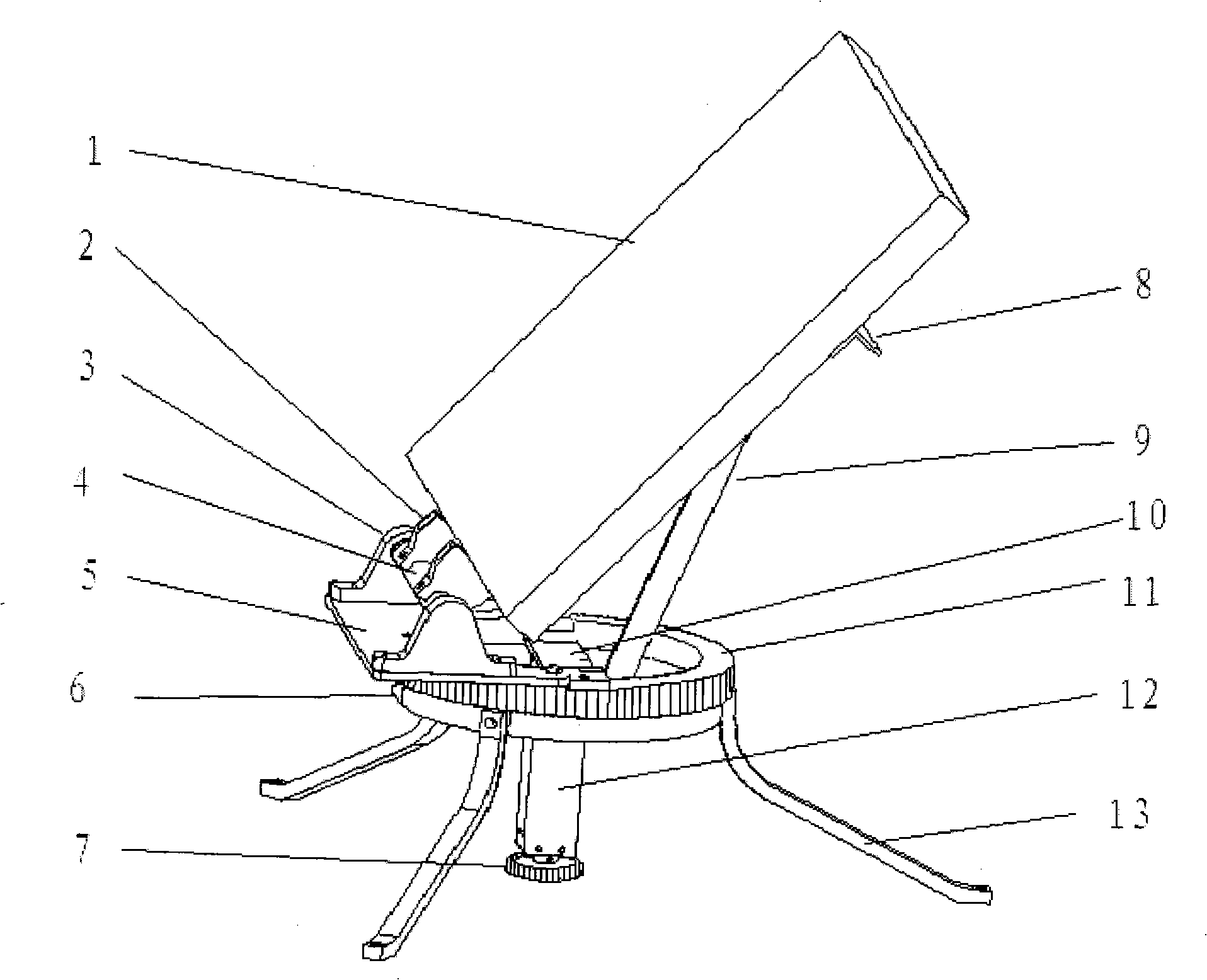
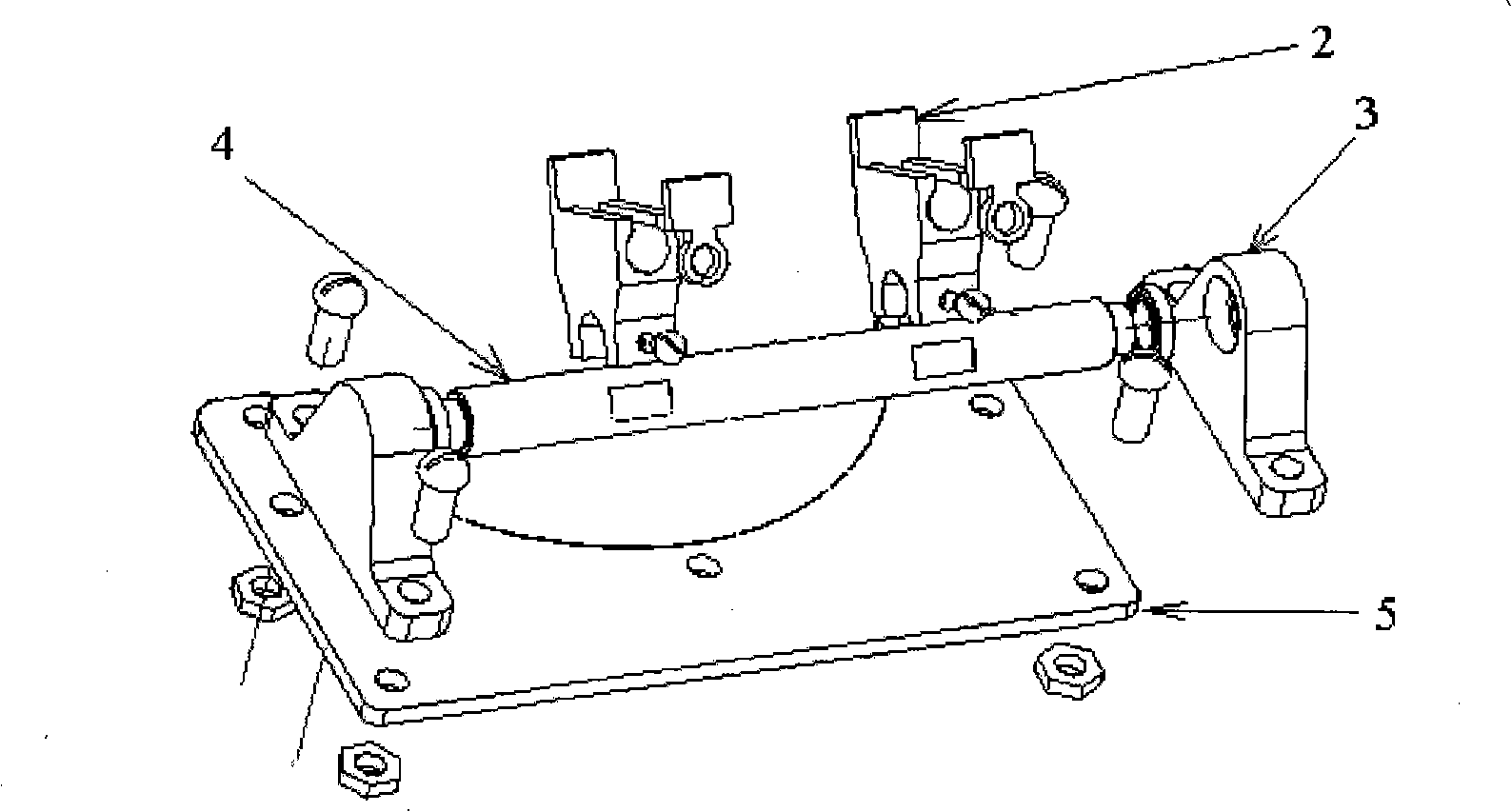
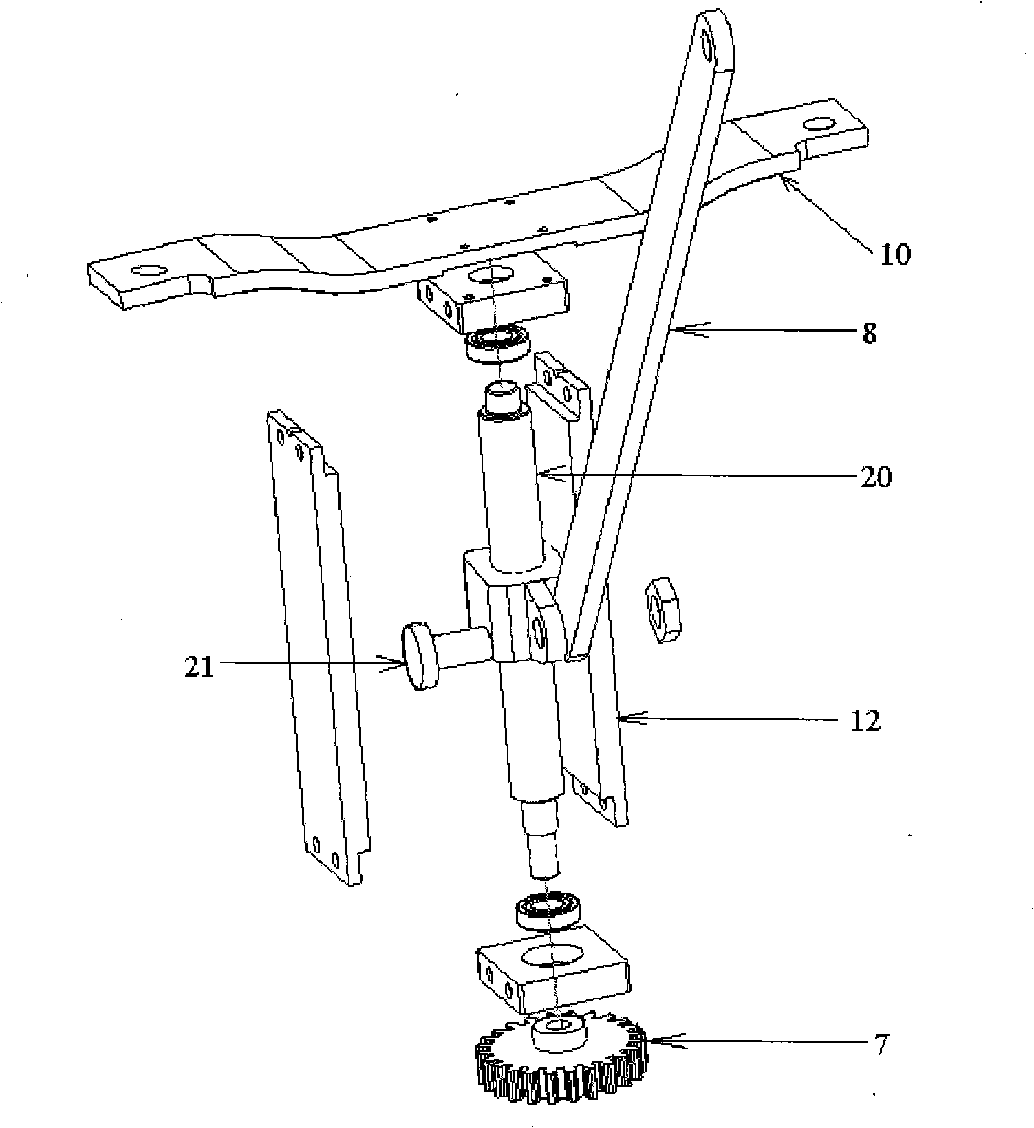
[0003] In order to overcome the shortcomings of low efficiency and short system life of traditional solar energy utilization devices, the present invention provides a solar tracker, including a mechanical movement part and a reset control part, wherein the mechanical part includes a horizontal revolving mechanism and a vertical pitching mechanism, and is characterized in that, The upper cover 5 is fixed on the large gear 11, and the upper cover 5 is provided with a bearing seat 3, which supports and fixes the pitching shaft 4, and a fixing clip 2 is set on the pitching shaft 4, and a support beam 8 is set on the back of the solar module 1, and the solar module 1 is fixed on the On the fixed clip 2, a horizontal turnover mechanism is formed; a screw mounting seat 10 is installed on the large gear 11, and a slider guide rail 12 is arranged on the lower part thereof. One end of the screw 20 is fixed on the screw mounting seat 10, and the other end passes through the sliding The block guide rail 12 is provided with a pinion 7 at the end, and a slider 22 is arranged on the lead screw. One end of the transmission rod 9 is connected with the slider 22, and the other end is connected with the support beam 8 to form a vertical pitching mechanism; the large gear 11 is installed On the base 6; a microswitch trigger piece 19 is set on the base 6, two microswitches 17 are set on the surface adjacent to the large gear 11 and the base 6, and a horizontal turnover drive motor 23 is fixed on the outer ring surface of the base 6 , it is connected with the horizontal epicyclic drive gear 24 meshed with the bull gear 11, the vertical pitch drive motor 25 is fixed outside the lower part of the slider guide rail 12, and the vertical pitch drive gear 26 meshed with the pinion 7 is connected on it, and the micro-motion The switch 17, the horizontal rotation drive motor 23 and the vertical pitch drive motor 25 are all connected to the control circuit to form a reset control part

Method used


Image

  • Sun tracker
  • Sun tracker
  • Sun tracker

Examples


Embodiment Construction

[0023] The present invention provides a solar tracker, and the present invention will be further described below through the description of the drawings and specific implementation methods.

[0024] The present invention includes a mechanical movement part and a reset control part, wherein the mechanical part includes a horizontal revolution mechanism and a vertical pitch mechanism, figure 1 It is a schematic structural diagram of the device system of the present invention; figure 2 It is an explosion diagram of the rotating shaft of the pitching mechanism of the present invention; image 3 It is an exploded view of the screw slider mechanism of the present invention; Figure 4 It is a schematic diagram of installation of the horizontal turnover drive motor of the present invention; Figure 5 It is a schematic diagram of the installation of the vertical pitch drive motor of the present invention; Image 6 It is a structural schematic diagram of the reset control part of th...


PUM


Abstract

The invention belongs to the field of the solar energy equipment, and in particular relates to a solar tracker, which comprises a mechanical movement part and a reset control part; wherein, the mechanical part comprises a horizontal epicyclic mechanism and a vertical pitch mechanism; a photosensitive element is arranged on solar components; and by sensing the sunlight intensity and controlling the operation of a motor by a control circuit, the sun tracking is realized. With flexible movement, low processing cost and higher reliability, the angle of the vertical pitch mechanism of the solar tracker ranges between 20 and 70 degrees; after the reset control part drives the solar tracker to move from a starting position to a preset ending position, the solar tracker is automatically reset along the original trajectory, thus avoiding the winding problems of wires and water pipes caused by the circular motion; the system can render the sunlight reception surface of the solar energy components in working state to be in perpendicular to the sunlight so as to effectively receive the sunlight and improve the working efficiency; and the entire system has the advantages of simple structure, low manufacturing cost, reliable control and high precision.

Description

technical field [0001] The invention belongs to the field of solar equipment, in particular to a sun tracker. Background technique [0002] The traditional solar energy utilization system mainly uses a fixed installation method to receive sunlight. According to the geographical latitude of the location, the sunlight receiving surface of the system is fixed at a certain angle to the horizontal plane and fixed to the south. The sun rotates from east to west relative to the earth on a one-day cycle, and rotates back and forth along the earth's Tropic of Cancer on a one-year cycle. Therefore, the angle between the receiving surface of the system and the sunlight in the traditional installation method is constantly changing, and the utilization rate of solar energy is different in different time periods, that is to say, the average utilization rate of solar energy is low, and the system receives solar energy sooner or later, and in spring and summer. Within the range of change, ...

Claims


Application Information

Patent Timeline
IPC IPC(8): F24J2/38F24S50/20H02S20/32
CPCY02E10/47Y02E10/50
Inventor 郭一竹胡妃俨廉松海房海蓉
Owner 温州中硅科技有限公司
Learn More