
Method of producing for self-generating carbide particle reinforced ferrite heat-resistant steel

A manufacturing method and ferrite technology, applied in the field of metallurgy, can solve the problems of small expansion coefficient anti-deformation ability and oxidation resistance, small thermal expansion coefficient anti-deformation ability, anti-deformation ability and poor wear resistance, etc., to facilitate industrial production , Low product cost and strong market competitiveness

Inactive Publication Date: 2010-06-02
JINAN JIGANG IRON ALLOY FACTORY
View PDF9 Cites 0 Cited by
  • Summary
  • Abstract
  • Description
  • Claims
  • Application Information

AI Technical Summary

Problems solved by technology

[0006] (1) Ordinary cast iron: low cost, poor overall performance, and is rarely used at present
(2) Heat-resistant cast iron: high brittleness, poor oxidation resistance, short service life, rarely used at present
(3) High chromium cast iron: good high temperature oxidation resistance, high hardness, good wear resistance, small thermal expansion coefficient, strong deformation resistance, but poor toughness
(4) Austenitic heat-resistant steel: good high-temperature oxidation resistance and high-temperature strength, high plasticity and toughness, but large expansion coefficient, poor deformation resistance and wear resistance, and high cost
(5) Ferritic heat-resistant steel: small expansion coefficient, good deformation resistance and oxidation resistance, but its high temperature performance still needs to be improved
[0007] With the improvement of sinter output and quality requirements, the increase of sinter thickness, the extension of sintering temperature and time, the properties of grate materials, especially high temperature oxidation resistance, high temperature strength, high temperature wear resistance and thermal fatigue resistance, etc. higher requirements, traditional materials have been difficult to meet the requirements

Method used


Image

  • Method of producing for self-generating carbide particle reinforced ferrite heat-resistant steel
  • Method of producing for self-generating carbide particle reinforced ferrite heat-resistant steel
  • Method of producing for self-generating carbide particle reinforced ferrite heat-resistant steel

Examples


Embodiment 1

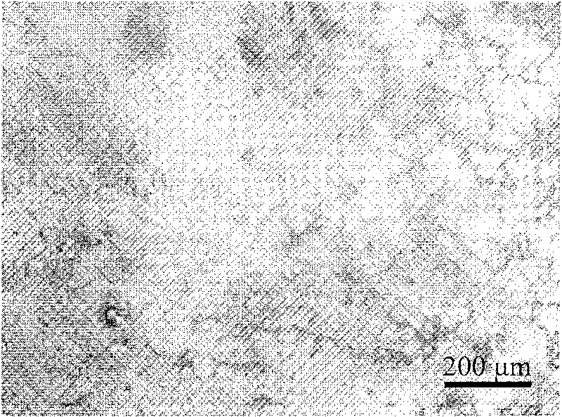
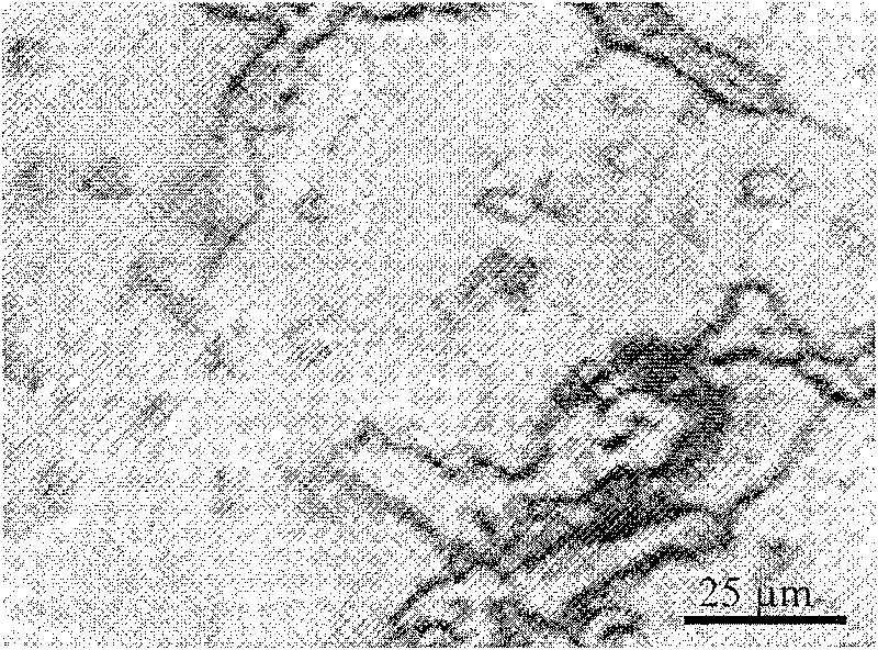
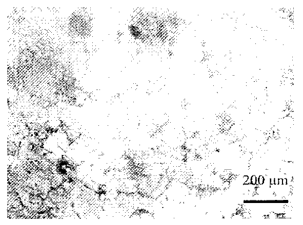
[0036] The preparation method of the heat-resistant steel in Example 1 is as follows: in a 1 ton induction furnace, first melt the furnace charge and steel scrap, then add the ferroalloy containing C, Si, Mn, Cr, Mo, RE, and take a sample after it is completely melted and uniform Analyze the composition and adjust according to the analysis results to make the content of each element in the heat-resistant steel reach the standard, raise the temperature of the molten steel to above 1520°C for slag removal, deoxidation, and superheat to 1540-1560°C, and tap at 1540°C-1580°C , for composite processing. The composite treatment process is as follows: when the amount of molten steel is 1 / 3 of the total amount of the ladle, add ferro-titanium, ferro-vanadium and ferro-niobium alloy particles preheated at 200°C to 300°C. The molten steel is poured at 1500°C to 1520°C after appropriate mechanical stirring and slag removal to obtain castings. The preparation method of embodiment 2 and 3...


PUM

PropertyMeasurementUnit
sizeaaaaaaaaaa
sizeaaaaaaaaaa

Abstract

The invention relates to in-situ carbide particle strengthening ferrite heat-resistant steel used in a sintering machine cage bar and a manufacturing method thereof, wherein the heat-resistant steel contains 0.6-1.2 percent of C, 1.0-1.5 percent of Si, 0.5-1.0 percent of Mn, 18-26 percent of Cr, 0.2-1.0 percent of Mo, 0.05-0.15 percent of Re, 0.05-0.2 percent of Al, less than 0.03 percent of S, less than 0.05 percent of P, 0.5-3 percent of more than one of Ti, V and Nb by weight percent, and the rest parts are iron and inevitable impurities. The manufacturing method comprises the following steps of: melting the raw materials for manufacturing ferrite heat-resistant steel matrix alloy in an induction furnace, heating up the molten steel to higher than 1520 DEG C, removing slag, deoxidizing,overheating to 1540-1560 DEG C, tapping and carrying out compounding treatment. The invention which remarkably improves the performance of the heat-resistant steel and prolongs the service life of the sintering machine cage bar has the advantages of simple manufacturing method, easy industrial production and lower production cost.

Description

technical field [0001] The invention relates to an authigenic carbide particle-reinforced ferrite heat-resistant steel used for a sintering machine grate bar and a manufacturing method thereof, belonging to the technical field of metallurgy. Background technique [0002] The sintering machine is the key equipment of iron and steel metallurgy, and the grate bar is the key wearing part of the sintering machine. Its working temperature changes periodically in the range of 100-1000°C; during the high-temperature sintering process, it bears the gravity of sintered ore, the high-speed impact and wear of the two airflows of powder gas, and the oxidation and corrosion of carbon monoxide, carbon dioxide, sulfur dioxide and water vapor in the atmosphere. ; During the unloading process, it bears the mechanical wear of the sinter; in addition, there are mechanical vibrations during the operation, mechanical impact during the cleaning process, etc. The combined effect of high temperatur...

Claims


Application Information

Patent Timeline
Patent Type & Authority Patents(China)
IPC IPC(8): C22C38/38C21C5/52C21C7/00
Inventor 于化顺郭洪卫孙武汪永烈李义林赵欣
Owner JINAN JIGANG IRON ALLOY FACTORY
Learn More