Image forming apparatus
An image and non-image technology, which is applied to corona discharge devices, electrical recording processes using charge patterns, equipment for electrical recording processes applying charge patterns, etc., and can solve problems such as discarding and image quality deterioration.
- Summary
- Abstract
- Description
- Claims
- Application Information
AI Technical Summary
Problems solved by technology
Method used
Image
Examples
no. 1 example
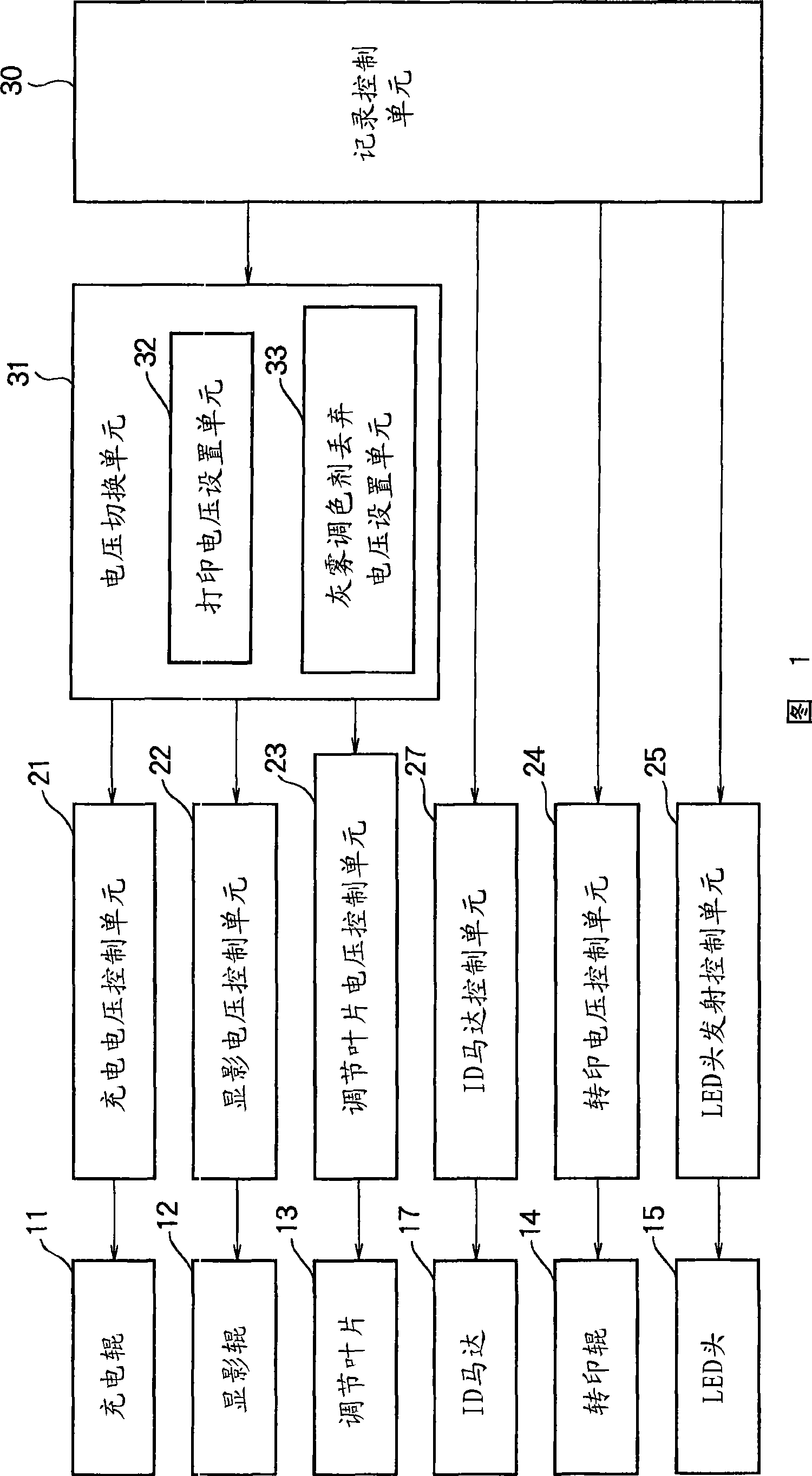
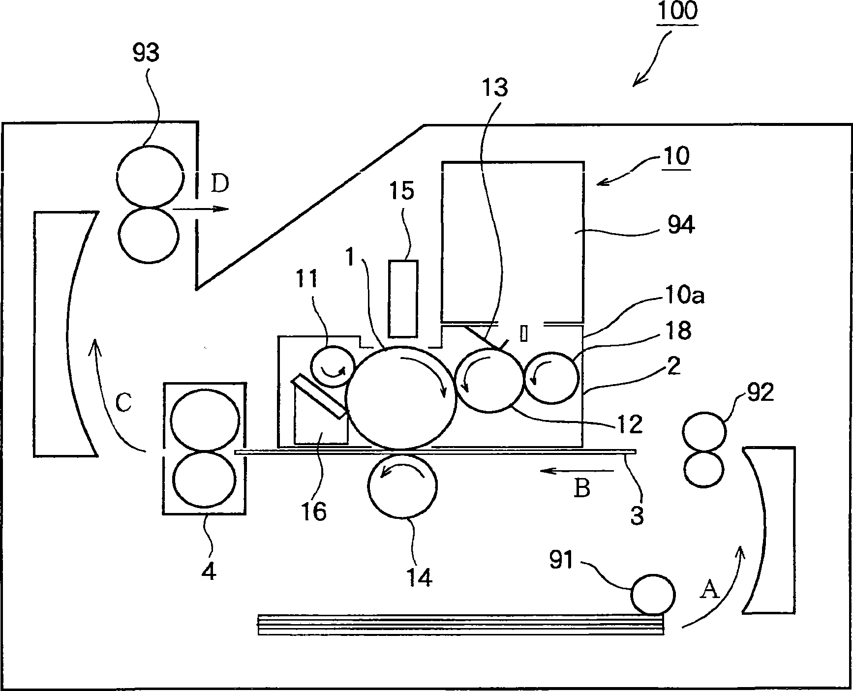
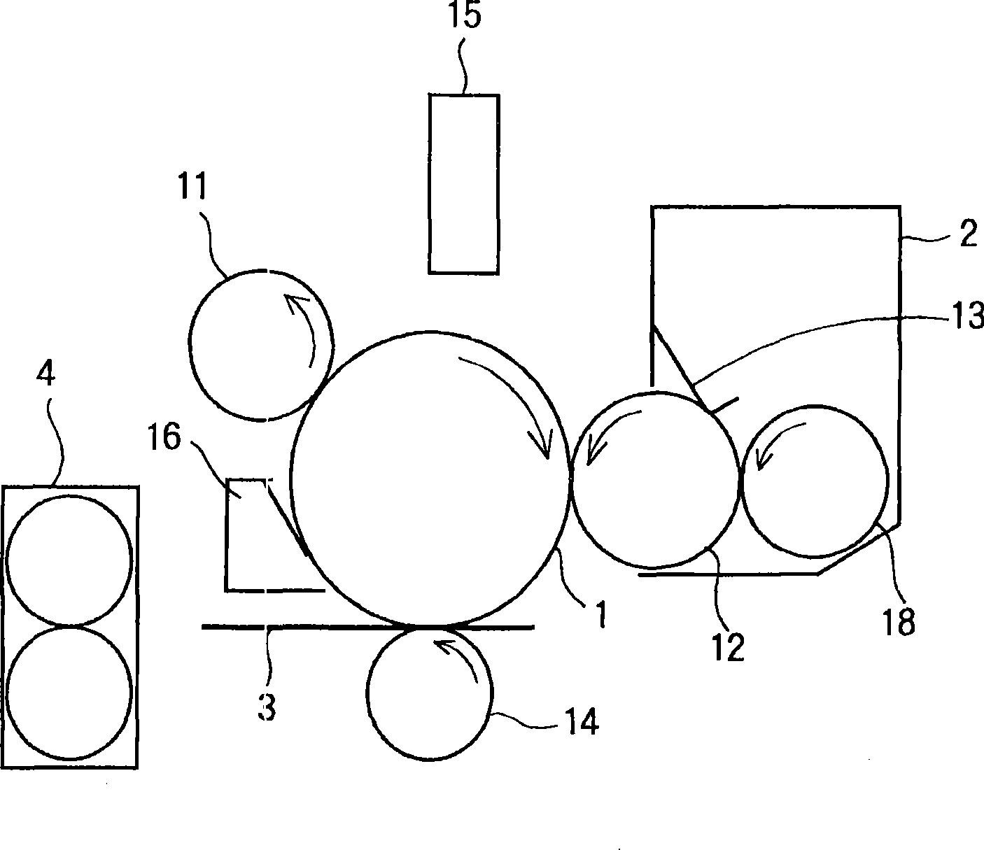
[0035] FIG. 1 is a block diagram showing a control system of an image forming apparatus according to a first embodiment of the present invention. figure 2 is a sectional view showing the image forming apparatus according to the first embodiment of the present invention. image 3 is a schematic diagram showing main components of the image forming apparatus according to the first embodiment of the present invention.
[0036] The image forming apparatus 100 according to the present embodiment may be any type of image forming apparatus such as a printer, a facsimile machine, a copier, a compound machine (having various functions), and the like. Here, the image forming apparatus 100 takes the form of an electrophotographic printer that forms images using electrophotography. Although the image forming apparatus 100 may be configured to form a color image, for convenience of explanation, the image forming apparatus 100 will be described as an image forming apparatus that forms a mon...
no. 2 example
[0147] Next, a second embodiment of the present invention is described. The same components as those of the first embodiment are given the same reference numerals, and their explanations will be omitted. Regarding the same operations and advantages as those of the first embodiment, their explanations will be omitted.
[0148] 11 is a block diagram showing a control system of an image forming apparatus according to a second embodiment of the present invention.
[0149] In the first embodiment, a configuration for discarding fog toner is described. However, in a low humidity environment (eg, at 10% humidity), overcharged toner (ie, highly charged toner) may cause smearing. Therefore, in this second embodiment, a configuration for discarding such smudged toner is described.
[0150] As shown in FIG. 11 , in the second embodiment, the charging voltage control unit 21 , the developing voltage control unit 22 and the regulation blade control unit 23 are connected to the voltage s...
no. 3 example
[0231] 18 is a block diagram of a control system of an image forming apparatus according to a third embodiment of the present invention. The same components as those of the first or second embodiment are given the same reference numerals, and explanations thereof will be omitted. Regarding the same operations and advantages as those of the first or second embodiment, explanations thereof are omitted.
[0232] In the third embodiment, the charging voltage control unit 21 , the developing voltage control unit 22 and the regulating blade control unit 23 are connected to the voltage switching unit 51 . The voltage switching unit 51 includes a printing voltage setting unit 52 , a fogging toner discarding voltage setting unit 53 , and a stained toner discarding voltage setting unit 54 . According to an instruction from the recording control unit 30, the voltage switching unit 51 selects a voltage used during printing (held in the printing voltage setting unit 52), a voltage used du...
PUM
 Abstract
Description
Claims
Application Information
 - Generate Ideas
- Intellectual Property
- Life Sciences
- Materials
- Tech Scout
- Unparalleled Data Quality
- Higher Quality Content
- 60% Fewer Hallucinations
Browse by: Latest US Patents, China's latest patents, Technical Efficacy Thesaurus, Application Domain, Technology Topic, Popular Technical Reports.
© 2025 PatSnap. All rights reserved.Legal|Privacy policy|Modern Slavery Act Transparency Statement|Sitemap|About US| Contact US: help@patsnap.com


