
Motor rotor position sensor and method for measuring position of motor rotor

A technology of motor rotor and sensor, applied in the direction of converting sensor output, measuring device, using electromagnetic/magnetic device to transmit sensing components, etc., can solve the problem of low measurement accuracy, eliminate distance changes and temperature changes, low cost, structure simple effect

Active Publication Date: 2009-04-01
CHERY AUTOMOBILE CO LTD
View PDF0 Cites 17 Cited by
  • Summary
  • Abstract
  • Description
  • Claims
  • Application Information

AI Technical Summary

Problems solved by technology

At present, there are two main methods to accurately detect the rotor position: the position sensor measurement method and the position sensorless technology to measure the rotor position. The position sensor method mainly includes the application of encoder, resolver and Hall position sensor technology to detect the rotor position signal. ;Whether it is an encoder, a Hall position sensor or a resolver, there are related circuits to determine the rotor position, which will be affected by the magnetic field of the motor stator winding when used, and some sensors such as resolvers are also measured when the motor rotor speed is low low precision

Method used


Image

  • Motor rotor position sensor and method for measuring position of motor rotor
  • Motor rotor position sensor and method for measuring position of motor rotor
  • Motor rotor position sensor and method for measuring position of motor rotor

Examples


Embodiment Construction

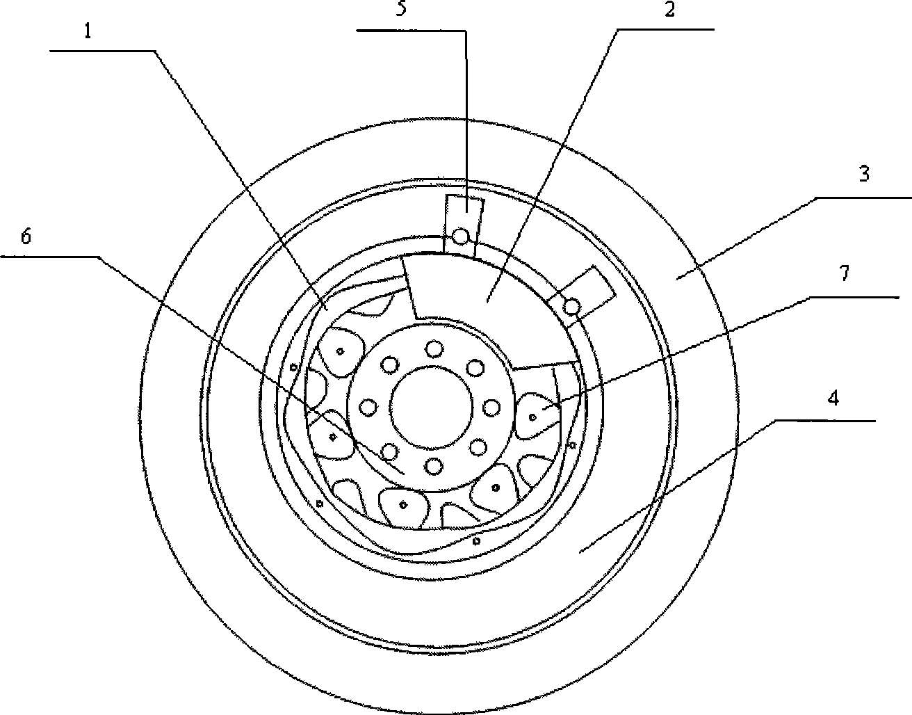
[0025] like figure 1 It is a schematic diagram of the installation of the rotor position sensor in an embodiment of the present invention, as shown in the figure: the rotor position sensor of the present invention includes an inductor 2 and a target disk 1, which are installed at one end of the motor, and the target disk 1 is an annular disk, which is The shape of the outer pattern is a sine curve or a cosine curve, and is made of metal materials such as aluminum or iron. It is installed and fixed on the rotor 4 bracket 7 and rotates around the rotor bracket axis 6 together with the rotor 4. The sensor 2 is installed through the sensor mounting bracket 5 On one side of the stator 3, the inductor 2 includes a planar winding and an ASIC (Application Specific Integrated Circuit) that processes the signals induced by the planar winding. The ASIC circuit is designed, manufactured and commercialized by Chery Automobile Company. The output is connected to TMS320f2808 DSP chip.

[00...


PUM


Abstract

The invention discloses a motor rotor position sensor and a method which precisely measures the rotor position by the sensor; the rotor position sensor comprises an objective disc which is arranged on the objective rotor, provided with a sine / cosine curved shape and made of conductive, an inductive element which is fixed in the shell of a motor, corresponding to the objective disc and provided with a plane winding, and an ASIC circuit which is connected with the induction circuit; the method completes the operation of precisely measuring the rotor position by using a DSP to process the signal induced by the rotor position sensor; the sensor meets the automobile standard, is not affected by the magnetic field of the motor stator winding, and has the advantages of high performance and low cost. The method used for precisely measuring the position and rotation speed of the rotor of the motor can be uniformly completed by the DSP device; therefore, the sensor and the method can precisely measure the position and speed of the motor rotor; furthermore, the device has simple structure and low cost.

Description

technical field [0001] The invention relates to a sensor and a measurement method using the sensor, in particular to a sensor used in a hybrid electric vehicle to measure the rotor position of a permanent magnet synchronous motor as a hybrid electric motor. A sensor based on the principle of eddy current effect, a method of accurately measuring the rotor position using this sensor. Background technique [0002] In order to ensure the smooth rotation of the motor and the precise control of the motor, it is not only necessary to control the armature current, but also to detect the accurate rotor position. Accurate rotor position detection can ensure that the sine curve of the motor current is synchronized with the corresponding rotor position, avoiding the conduction commutation torque fluctuation. At present, there are mainly two methods to accurately detect the rotor position: the position sensor measurement method and the method without position sensor technology to measur...

Claims


Application Information

Patent Timeline
Patent Type & Authority Applications(China)
IPC IPC(8): G01D5/14H02K29/06H02K19/14
CPCG01D5/2053H02P6/18
Inventor 谢美娟
Owner CHERY AUTOMOBILE CO LTD
Learn More