
Power tool

A power tool and torque adjustment technology, applied in the field of power tools, can solve problems such as short axial length of the fuselage

Active Publication Date: 2009-04-01
POSITEC POWER TOOLS (SUZHOU) CO LTD
View PDF2 Cites 9 Cited by
  • Summary
  • Abstract
  • Description
  • Claims
  • Application Information

AI Technical Summary

Problems solved by technology

In the setting of this clutch disclosed in the European patent, the spring is arranged axially, but the force of the steel ball, including the force direction of the steel ball to the ring gear, is radial, and both the spring and the steel ball are On the periphery of the inner ring gear, the space required in the axial direction overlaps most of the inner ring gear, so this clutch arrangement makes the axial body length of the entire tool relatively short

Method used


Image

  • Power tool
  • Power tool
  • Power tool

Examples


Embodiment Construction

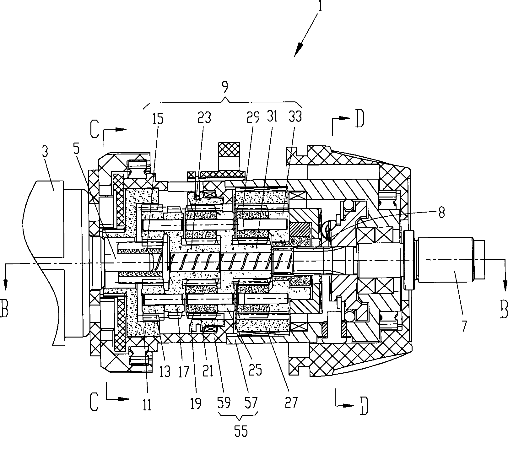
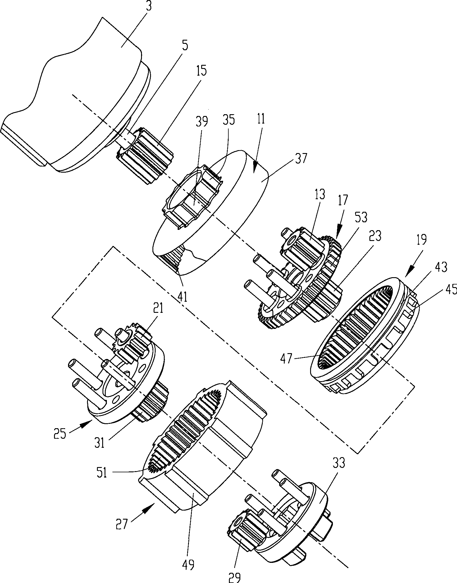
[0025] refer to Figure 1 to Figure 2 , a three-function impact drill 1, can be operated in one of three modes of screwdriver, drilling and impact. The three-function hammer drill 1 includes a motor 3 having a rotating motor output shaft 5 for transmitting the rotational motion of the motor 3 to a spindle 7 . The main shaft 7 is located at the front end of the hammer drill 1 for driving the working head (not shown), and the rear end of the main shaft 7 is provided with an external spline 8 . A gear reduction mechanism 9 is provided between the motor 3 and the main shaft 7 , and the reduction gear mechanism 9 is used to reduce the higher rotational speed of the output shaft 5 of the motor and then transmit it to the main shaft 7 .

[0026] The gear reduction mechanism 9 includes a three-stage planetary gear set, the first-stage planetary gear set includes a first ring gear 11, the first planetary gear 13 meshes with the first ring gear 11, and the first sun gear 15 meshes with...


PUM


Abstract

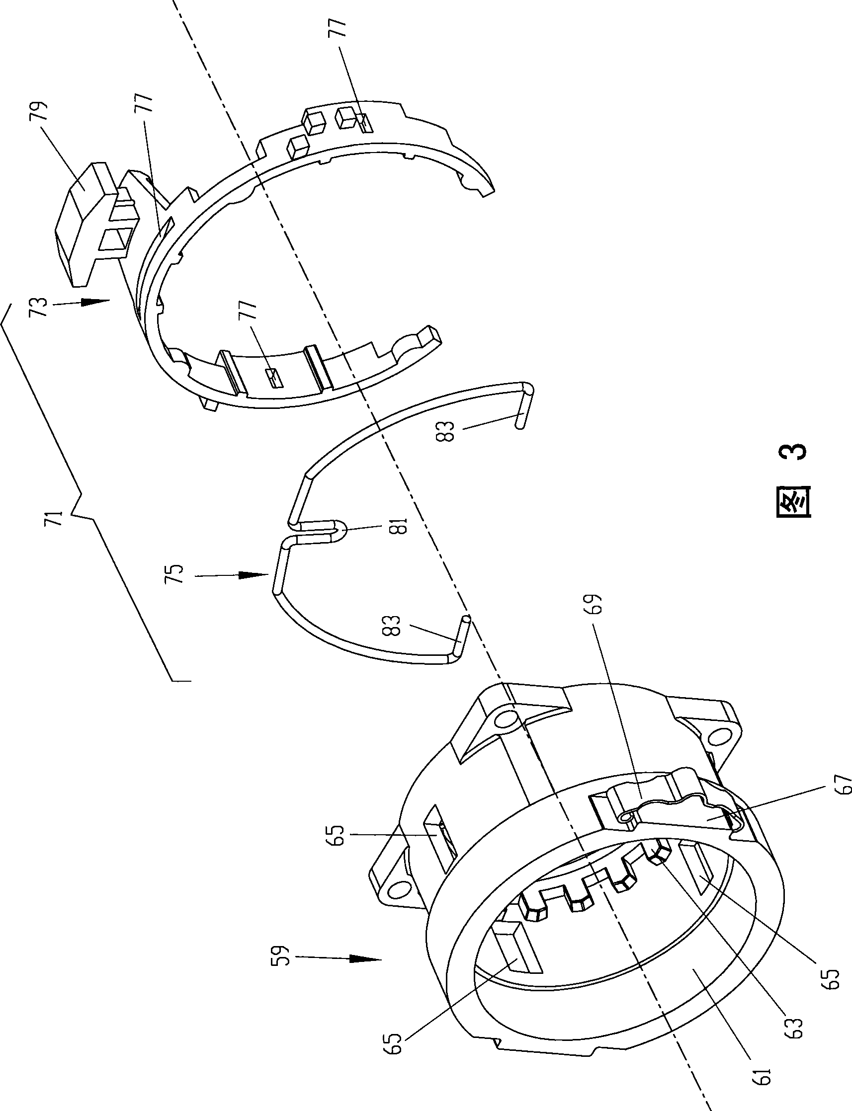
The invention provides a power tool, comprising a motor, a shell, and a gear reducing mechanism which is driven by the motor and is arranged in the shell; the gear reducing mechanism comprises an internal tooth ring which can be contained in the shell in a rotatable way; the power tool also comprises a clutch mechanism which comprises a pushing element and an elastic element, and a torque adjusting element; the external surface of the internal tooth ring is provided with at least a concave trough; the pushing element is arranged in any concave trough movably; the elastic element which can be deformable in radial direction is arranged between the pushing element and the torque adjusting mechanism, thus leading the elasticity of the elastic element to be changed by adjusting the torque adjusting element.

Description

technical field [0001] The invention relates to a power tool, such as a screwdriver, an electric drill with dual modes of screwdriver and drilling, and an impact drill with three modes of screwdriver, drilling and impact. A power tool that outputs an upper limit of torque. Background technique [0002] U.S. Patent No. 6,523,658B2 discloses an electric drill with a screwdriver mode and a drilling mode, the electric drill includes a motor, the motor has an output shaft, and a gear reduction mechanism is provided at the front of the motor, and the gear reduction mechanism includes The three-stage planetary gear, the three-stage planet carrier for rotating the supporting planetary gear and the three-stage ring gear mesh with the planetary gear respectively. The gear reduction mechanism reduces the speed of the output shaft of the motor and then transmits it to the main shaft connected with the third-stage planet carrier. The clutch mechanism is located at the front part of the...

Claims


Application Information

Patent Timeline
IPC IPC(8): B25B23/14B25B21/00F16D43/20
Inventor 何明明张伟
Owner POSITEC POWER TOOLS (SUZHOU) CO LTD
Learn More