
Composite spout, and injection molding device for molding the same

A compound nozzle and injection molding technology, which is applied in packaging, transportation and packaging, and other household appliances, and can solve problems such as changes and reduced flavor of the contents

Active Publication Date: 2009-03-25
TOYO SEIKAN KAISHA LTD +1
View PDF1 Cites 4 Cited by
  • Summary
  • Abstract
  • Description
  • Claims
  • Application Information

AI Technical Summary

Problems solved by technology

As a result, the end surface 10g of the sleeve 10 is exposed, and when the content is filled, the functional resin is eluted from the functional resin layer 10a constituting the sleeve 10, causing problems in sanitation, or a decrease or change in the flavor of the content.

Method used


Image

  • Composite spout, and injection molding device for molding the same
  • Composite spout, and injection molding device for molding the same
  • Composite spout, and injection molding device for molding the same

Examples


Embodiment Construction

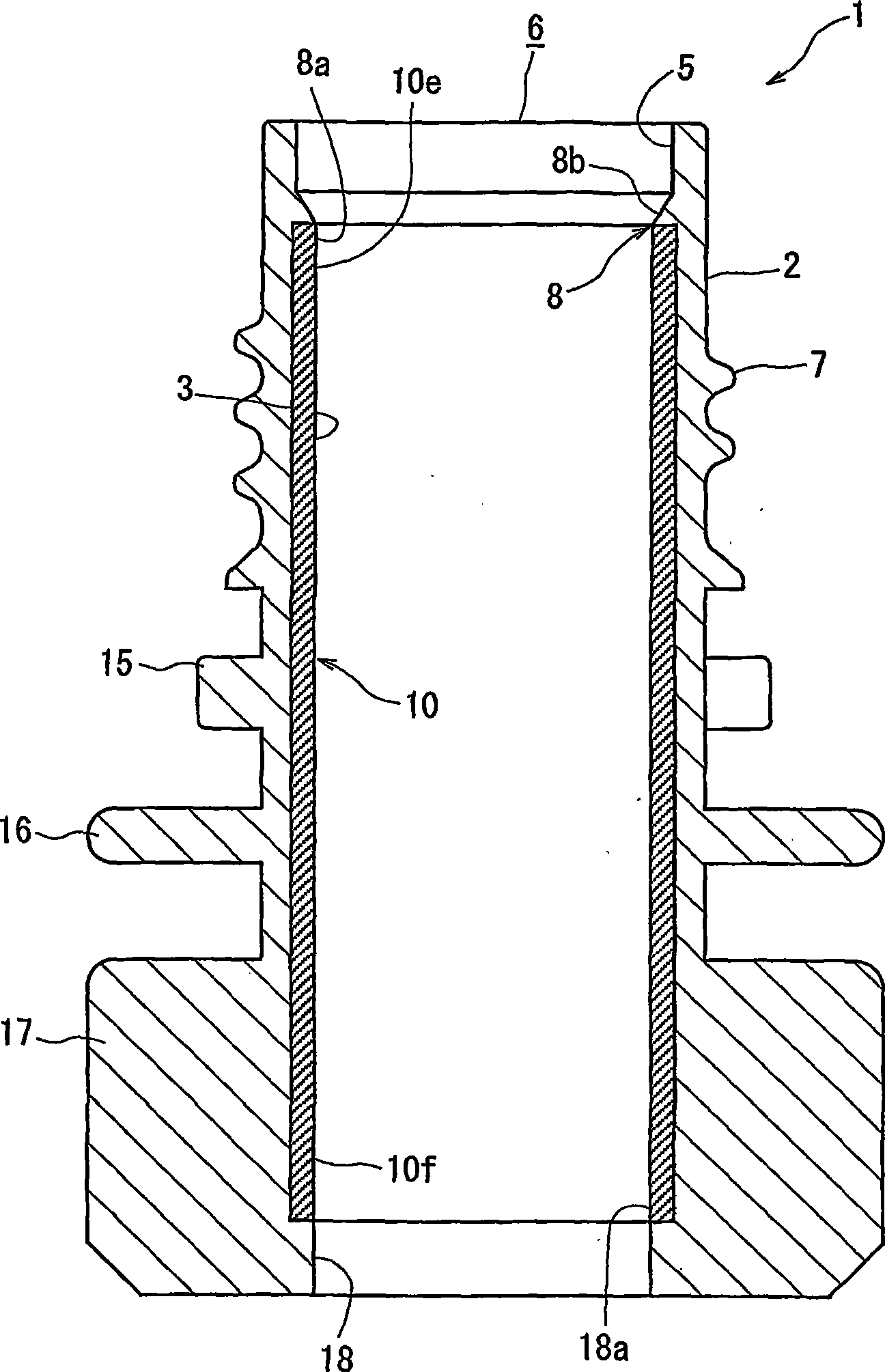
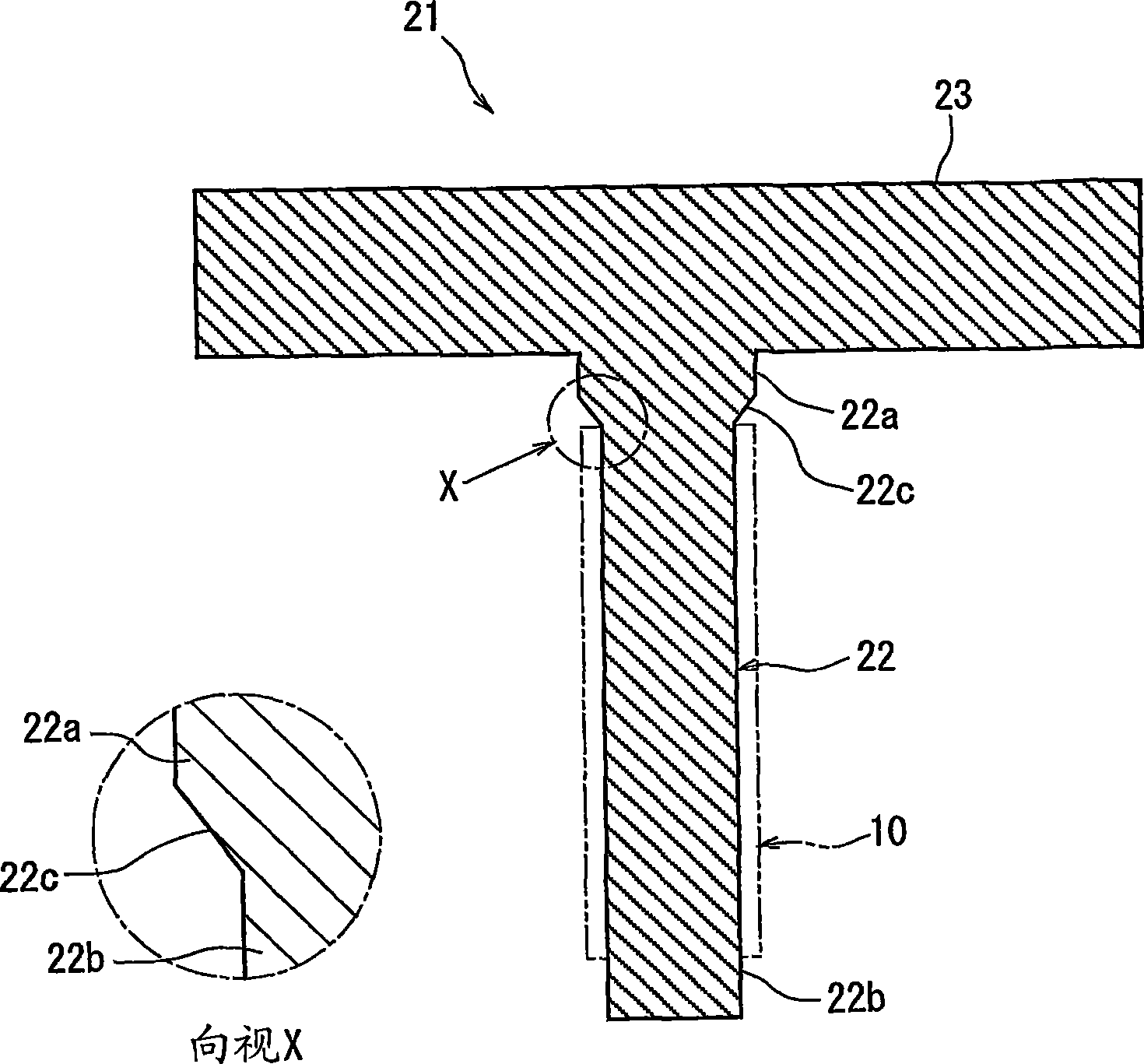
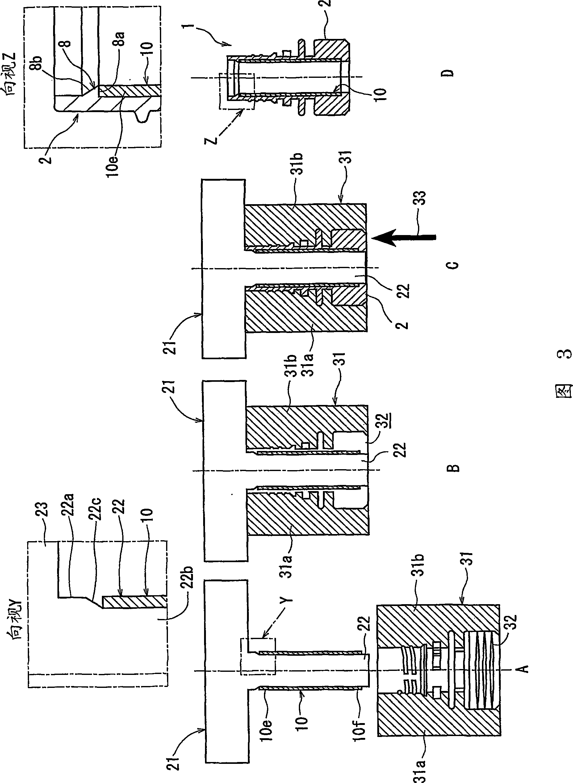
[0054] Next, the composite nozzle according to the first embodiment of the present invention and the injection molding apparatus for forming the composite nozzle will be described with reference to the drawings.

[0055] In addition, the bushing 10 described in the conventional example is as follows Figure 16 As shown, the multilayer sleeve 10 is composed of five layers including an adhesive layer having the same structure as the sleeve 10 of the present embodiment, and therefore detailed description thereof will be omitted. In addition, the composite nozzle 1 has the side with the discharge opening 6 as the front end side, and the side with the mounting portion 17 as the base end side. The sleeve 10 has the discharge opening 6 side of the composite nozzle 1 as one end portion 10e, and has the attachment portion side of the composite nozzle 1 as the other end portion 10f. In addition, the shape of the sleeve 10 and the orientation of the composite nozzle are the same as in t...


PUM


Abstract

The present invention provides a composite spout and an injection molding apparatus for molding the composite spout. In the composite spout, a sleeve fitted to a core member is not displaced during injection molding and the end face of the sleeve is not exposed to the inside of a spout body. A functional resin layer is provided as an intermediate layer in the sleeve, a spout body is injection-molded with the sleeve that functions as a core and is put over the core member of an injection molding die. Therefore, substantially only the inner peripheral surface of the sleeve is exposed to the inner peripheral surface of the spout body. At least a circumferential part of one end of the inner peripheral surface of the spout body meets the inner peripheral edge on one end side of the sleeve or forms a slope radially outwardly tilting from the part of the spout body toward the one end of the spout body.

Description

technical field [0001] The present invention relates to a sleeve having functional resin that does not deviate during injection molding during manufacture, and is mounted on the nozzle body so that the end surface of the sleeve is not exposed to the air, or mounted on the nozzle body during manufacture. The upper casing is easy to be positioned in the composite nozzle in the forming mold during injection molding and the injection molding device forming the composite nozzle. Background technique [0002] In recent years, it is well known that there are filled high-functional foods, etc., and from Figure 14 and Figure 15 The shown dispensing tool (hereinafter referred to as nozzle) 1 is a container such as a pouch with a nozzle, a paper container, or the like that is poured out. In order to prevent deterioration of the content and decrease in flavor due to oxygen, the above-mentioned containers are required to have very little oxygen permeation not only in the main body of ...

Claims


Application Information

Patent Timeline
Patent Type & Authority Applications(China)
IPC IPC(8): B65D33/38B29C33/12B29C45/14B29L23/00
Inventor 黑泽高博竹内公生桥本胜己米川雄平石井修松谷仁臣
Owner TOYO SEIKAN KAISHA LTD
Learn More