
Automatic gain compensation and linear control method and device for power amplifier

A technology of automatic gain compensation and power amplifier, which is applied in the direction of gain control, amplification control, and improvement of amplifiers to reduce temperature/power supply voltage changes, etc. It can solve the problems of ineffective automatic gain compensation of power amplifiers, poor stability of gain compensation, and inability to gain Compensation and other issues

Inactive Publication Date: 2011-01-26
福建先创电子有限公司 +1
View PDF3 Cites 0 Cited by
  • Summary
  • Abstract
  • Description
  • Claims
  • Application Information

AI Technical Summary

Problems solved by technology

[0004] In order to solve the technical problems in the prior art that the automatic gain compensation effect of the power amplifier is not obvious, real-time gain compensation cannot be performed according to the slight change of temperature, and the stability of the gain compensation is poor, the present invention provides a power amplifier Automatic Gain Compensation Method
[0006] In order to solve the technical problem that the automatic gain compensation effect of the power amplifier is not obvious in the prior art, real-time gain compensation cannot be performed according to the slight change of temperature, and the stability of the gain compensation is poor, and the automatic gain compensation of the power amplifier and the The linear control method is effectively implemented, and the present invention also provides a power amplifier automatic gain compensation and linear control device

Method used


Image

  • Automatic gain compensation and linear control method and device for power amplifier
  • Automatic gain compensation and linear control method and device for power amplifier
  • Automatic gain compensation and linear control method and device for power amplifier

Examples


Embodiment Construction

[0022] Below in conjunction with accompanying drawing and embodiment the present invention will be further described:

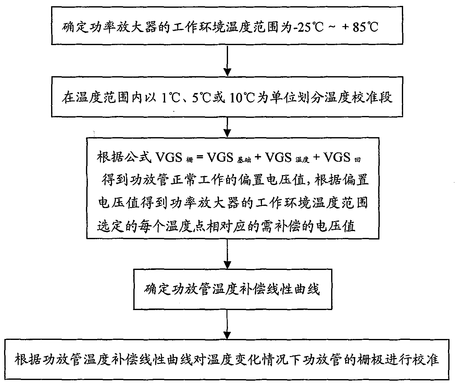
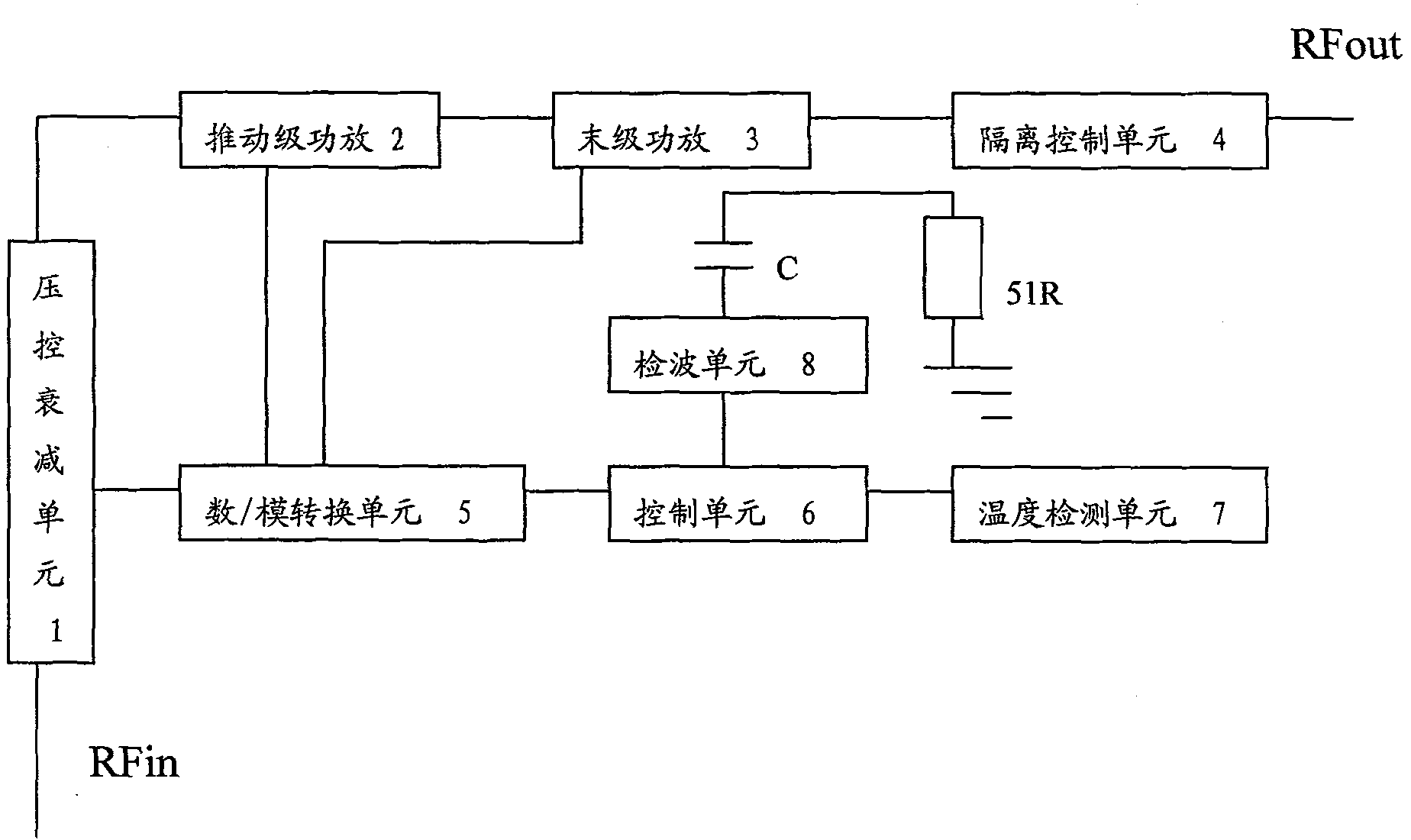
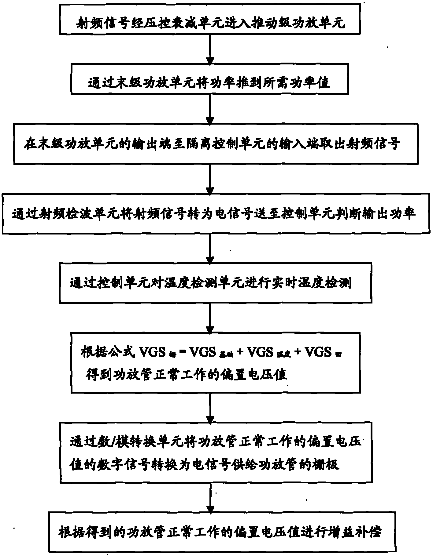
[0023] see figure 1 A flow chart of the automatic gain compensation and linear control method of the power amplifier and the automatic gain compensation method of the power amplifier in the device of the present invention. Such as figure 1 The power amplifier automatic gain compensation method shown, the power amplifier automatic gain compensation method includes the steps: the first step, converting the radio frequency signal into an electrical signal and sending it to the control unit 6 to determine the output power; the second step, through the control unit 6 Carry out temperature detection to temperature detection unit; The 3rd step, when temperature changes, described control unit 6 will compare the voltage value of 1V smaller than the bias voltage of power amplifier tube normal work, described power amplifier needs compensation under the real-time temp...


PUM


Abstract

The invention relates to a method for automatic gain compensation and linearity control method of a power amplifier and a device thereof. The method comprises the following steps: a radio frequency signal is converted into an electrical signal and sent to a control unit so as to judge an output power; the temperature detection is conducted for a temperature detecting unit through the control unit; when temperature changes, the control unit conducts the gain amplification for a bias voltage value of a power amplifier tube, which is obtained by adding a voltage value smaller than the bias voltage value 1V of the power amplifier in normal operation, a grid voltage value of the power amplifier which needs to be compensated under the condition of real-time temperature and a grid voltage value which needs to be compensated under the corresponding power output by the power amplifier, and corrects and compensates for a grid of the power amplifier tube when the temperature changes through a determinate linearity curve of temperature compensation of the power amplifier tube. The invention can ensure that the linearity indication of the power amplifier is little impacted by the temperature, and the power of the amplifier is between 1dB compression point and backing 9 dB. Furthermore, linearity always keeps an optimal parameter.

Description

technical field [0001] The technology of the present invention is suitable for high-linear high-power amplifiers, and is particularly suitable for radio-frequency power transistors LDMOS (Laterally Diffused Metal Oxide Semiconductor), radio-frequency integrated circuits, and high-linear high-power amplifiers controlled by single-chip microcomputers. Automatic gain compensation and linear control method and device of amplifier. Background technique [0002] In order to keep the linearity (IMD / ACPR) of the high-linearity power amplifier in the best condition in the range of -25°C to +85°C, it is necessary to carry out the gate voltage of the power amplifier tube at the corresponding temperature every time the temperature changes by 1°C. compensate. In a low temperature environment, the gain of the device becomes higher. In a high temperature environment, the gain of the device will be reduced. In order to keep the gain of the highly linear power amplifier stable in the rang...

Claims


Application Information

Patent Timeline
Patent Type & Authority Patents(China)
IPC IPC(8): H03F1/30H03G3/30
Inventor 陈玉辉刘聪江
Owner 福建先创电子有限公司
Learn More