
Stacking roller conveyor

An accumulating and releasing conveyor technology, applied in the field of conveyors, can solve the problems of high production cost, oil pollution, unfavorable operating environment, etc., and achieve the effect of reducing investment cost and improving the use environment.

Inactive Publication Date: 2009-03-25
MIRACLE AUTOMATION ENG CO LTD
View PDF0 Cites 29 Cited by
  • Summary
  • Abstract
  • Description
  • Claims
  • Application Information

AI Technical Summary

Problems solved by technology

[0002] The existing accumulation type roller conveyor adopts the structure of roller chain traction sprocket type accumulation roller, because the structure of the sprocket type accumulation roller itself is relatively complicated, the production cost is relatively high, which directly affects the investment of equipment cost; in addition, due to the lubrication needs of the chain itself, additional oil pollution will be generated, which is unfavorable to the surrounding operating environment

Method used


Image

  • Stacking roller conveyor
  • Stacking roller conveyor

Examples


Embodiment Construction

[0009] The present invention will be further described below in conjunction with specific drawings and embodiments.

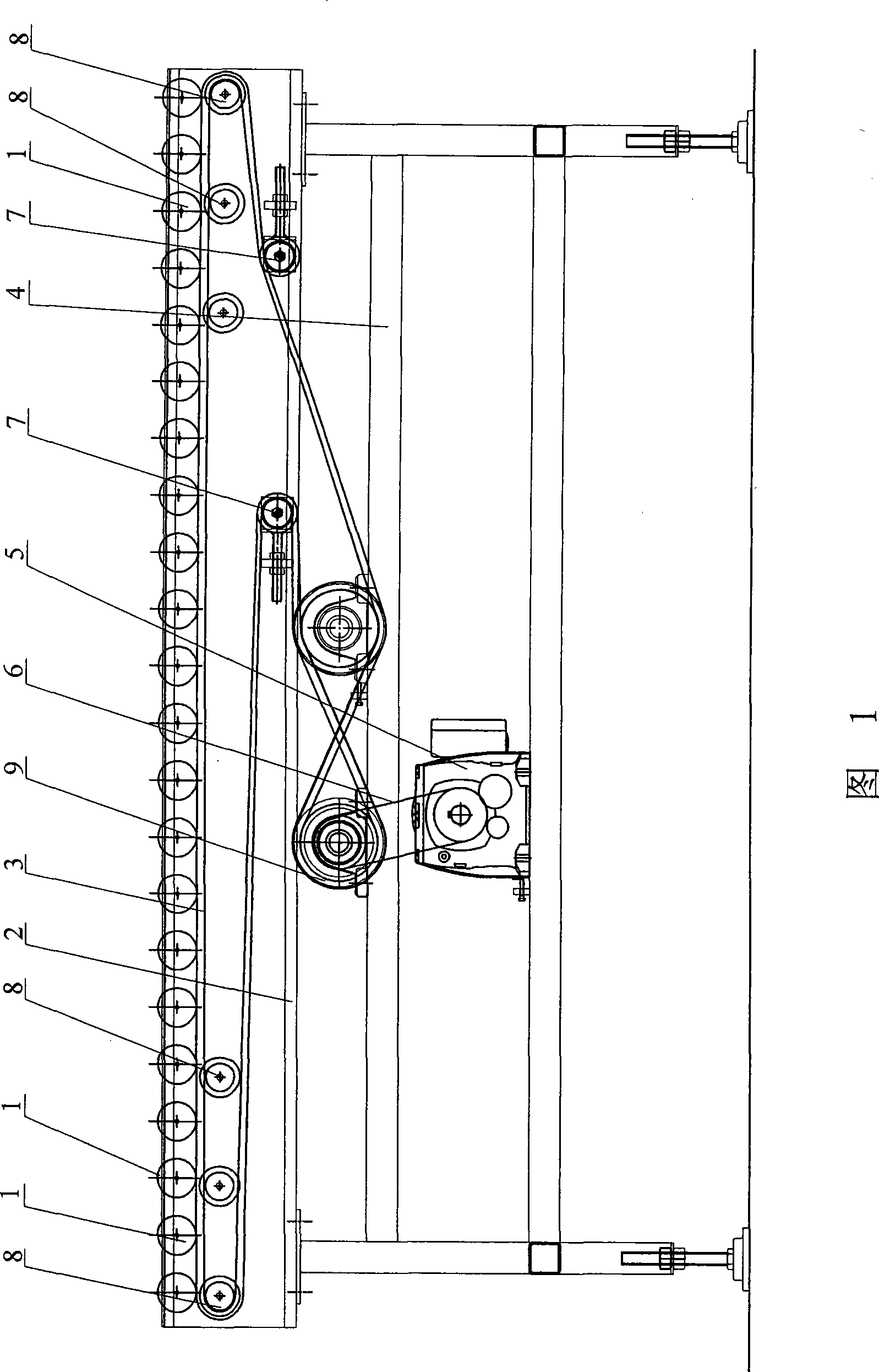
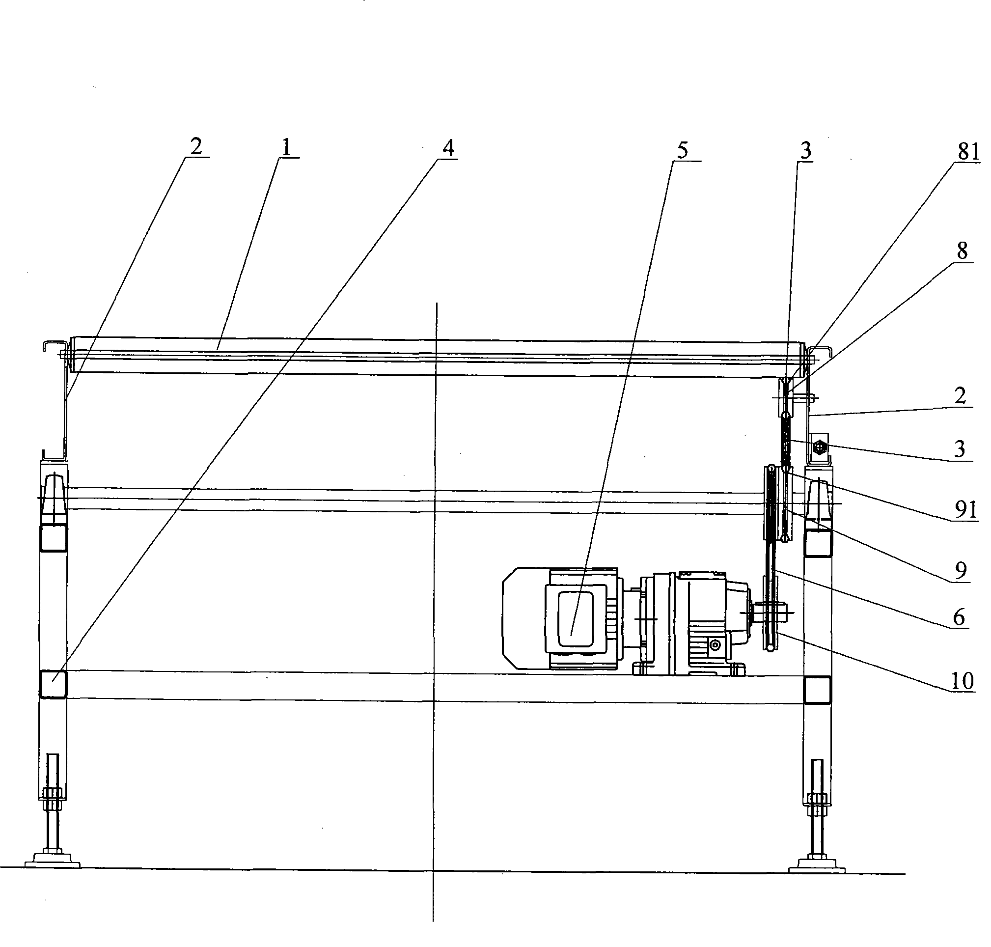
[0010] As shown in the figure: Installing plates 2 are arranged at intervals on the inner and outer sides of the upper end of the frame 4, and several rollers 1 are erected in parallel on the inner and outer mounting plates 2. The axes of all rollers 1 are in the same horizontal plane, at least on one side. The mounting plate 2 is rotatably connected with a transmission roller 8, the transmission roller 8 is arranged below the head and tail roller 1 in the conveying direction, and the outer wall of the transmission roller 8 is provided with a first depression 81 along its circumference. The frame 4 is rotatably connected with a passive roller 9, and the outer wall of the passive roller 9 is provided with a second recess 91 along its circumference, and the first recess 81 of the transmission roller 8 is embedded in the second recess 91 of the passive roller 9. T...


PUM


Abstract

The invention relates to a power-and-free roller conveyor belonging to the conveyor field. Mounting plates are arranged by interval on both the inner side and the outer side of the upper end of a frame; rollers are arranged parallel on the mounting plates of the inner and outer sides and all the axes of rollers are on the same plane; drive rollers are rotationally connected on the mounting plates of at least one side and the drive rollers are arranged below the rollers of both head part and tail part on the conveying direction; a first depression is arranged on the outer walls of the drive rollers, driven rollers are rotationally connected with the frame and a second depression is arranged on the outer walls of the driven rollers. An annular friction conveying-belt is respectively embedded inside the first depression and second depression. The friction conveying-belt is extended from the first depression to contact the outer walls of rollers and drive rollers; a driving apparatus is arranged on the frame and a driving wheel matching with the driven rollers is arranged on an output shaft of the driving apparatus; and a friction driving belt is respectively arranged around the driven rollers and drive rollers. The roller conveyor can largely reduce the investment cost for equipment and enhance the use environment of equipment.

Description

technical field [0001] The invention relates to an accumulation type roller conveyor in the field of conveyors. Background technique [0002] The existing accumulation type roller conveyor adopts the structure of roller chain traction sprocket type accumulation roller, because the structure of the sprocket type accumulation roller itself is relatively complicated, the production cost is relatively high, which directly affects the investment of equipment Cost; in addition, due to the lubrication needs of the chain itself, additional oil pollution will be generated, which is not good for the surrounding operating environment. Contents of the invention [0003] The object of the present invention is to overcome the deficiencies in the prior art, and provide a positive and free roller conveyor that can greatly reduce the investment cost of the equipment and can greatly improve the use environment of the equipment. [0004] According to the technical solution provided by the p...

Claims


Application Information

Patent Timeline
IPC IPC(8): B65G13/04B65G13/07B65G13/071
Inventor 张华兵沈锋李锋宝刘黎明
Owner MIRACLE AUTOMATION ENG CO LTD
Learn More