Aberration-correcting cathode lens microscopy instrument

一种像差校正、显微镜的技术,应用在仪器、科学仪器、放电管等方向,能够解决仪器设计和构造难以实现等问题

Active Publication Date: 2009-03-18
INT BUSINESS MASCH CORP
View PDF0 Cites 9 Cited by
  • Summary
  • Abstract
  • Description
  • Claims
  • Application Information

AI Technical Summary

Problems solved by technology

Combining all three elements into a single microscopy instrument has proven elusive in instrument design and construction

Method used


Image

  • Aberration-correcting cathode lens microscopy instrument
  • Aberration-correcting cathode lens microscopy instrument
  • Aberration-correcting cathode lens microscopy instrument

Examples


Embodiment Construction

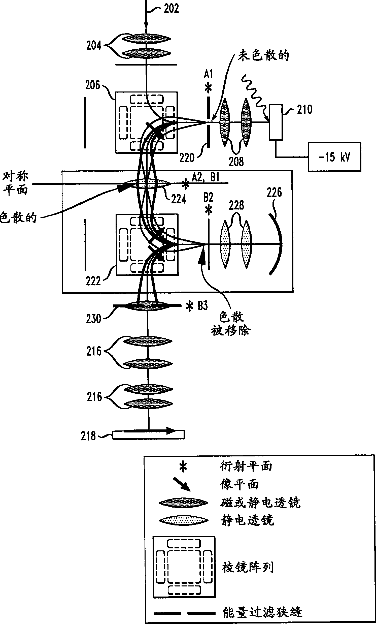
[0024] As described in detail below, the present invention introduces simplified aberration-corrected cathodic lens microscopy instruments. The novel microscope instrumentation and geometry of embodiments of the present invention greatly simplifies the task of aberration correction by replacing previously proposed electron optics with simpler devices.

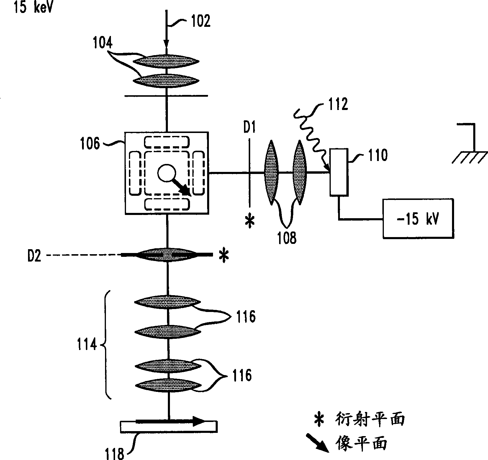
[0025] first reference figure 1 , shows a LEEM / PEEM instrument without aberration correction or energy filtering. In a LEEM instrument, an electron gun generates an electron beam 102 with an electron energy of, for example, 15 keV. A converging lens 104 focuses the electron beam 102 into a magnetic deflector 106 with a special prism array. The magnetic deflector 106 consists of two parallel plates between which electrons are deflected. Each plate of the magnetic deflector 106 preferably contains at least one, preferably five electromagnets. Magnetic deflector 106 deflects electron beam 102 by a large angle, for example 90 d...


PUM


Abstract

An aberration-correcting microscopy instrument is provided. The instrument has a first magnetic deflector (206) disposed for reception of a first non-dispersed electron diffraction pattern. The first magnetic deflector is also configured for projection of a first energy dispersed electron diffraction pattern in an exit plane (A2) of the first magnetic deflector. The instrument also has an electrostatic lens (224) disposed in the exit plane of a first magnetic deflector, as well as a second magnetic deflector (222) substantially identical to the first magnetic deflector. The second magnetic deflector is disposed for reception of the first energy dispersed electron diffraction pattern from the electrostatic lens. The second magnetic deflector is also configured for projection of a second non-dispersed electron diffraction pattern in a first exit plane (B2) of the second magnetic deflector. The instrument also has an electron mirror configured for correction of one or more aberrations in the second non-dispersed electron diffraction pattern. The electron mirror (226) is disposed for reflection of the second non-dispersed electron diffraction pattern to the second magnetic deflector for projection of a second energy dispersed electron diffraction pattern in a second exit plane (B3) of the second magnetic deflector.

Description

[0001] Cross References to Related Applications [0002] This application is related to Attorney Dock's US Patent Application No. YOR920050576US1, entitled "Energy-Filtering Cathode Lens Microscopy Instrument," which is hereby filed and incorporated by reference. technical field [0003] The present invention relates generally to electron microscopy, and in particular to simplified aberration-corrected electron microscopy instruments. Background technique [0004] Low Energy Electron Microscopy (LEEM) and Photoelectron Emission Microscopy (PEEM) are both examples of cathode lens microscopy, in which a strong electric field is maintained between the sample under study and the objective lens of the microscope. In this instrument, the sample is considered to be the cathode and the objective lens is considered to be the anode. At low energies, eg less than 500 eV, electrons are reflected from the sample in the case of LEEM instruments, or photons are emitted from the sample in ...

Claims


Application Information

Patent Timeline
Patent Type & Authority Applications(China)
IPC IPC(8): H01J37/05H01J37/153G01N23/20G01N23/227
CPCH01J37/05H01J37/153H01J2237/2544H01J2237/055H01J37/295H01J2237/1534H01J2237/2538H01J37/252
Inventor R·M·特罗普
Owner INT BUSINESS MASCH CORP
Why Eureka
Try Eureka