Planetary roller reduction gear
A technology of planetary rollers and reducers, which is applied in the direction of electromechanical devices, mechanical equipment, and control of mechanical energy, can solve problems such as micro wear and power loss, and achieve the effect of improving workability and reliability
- Summary
- Abstract
- Description
- Claims
- Application Information
AI Technical Summary
Problems solved by technology
Method used
Image

Examples
no. 1 approach
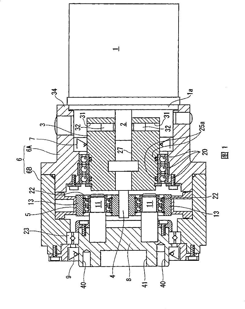
[0078] The present invention describes a first embodiment of a planetary roller speed reducer according to the present invention with reference to FIGS. 1 to 6 .
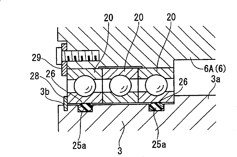
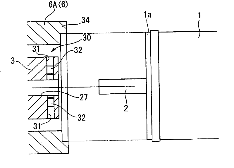
[0079] The planetary roller reducer in this embodiment, as shown in Figure 1, is a reducer of the type that is directly connected (directly connected) to the output shaft 2 of the motor 1, and has a housing 6, an input shaft 3, an input side oil seal 7, an input Side ball bearing (bearing for input shaft) 20 , sun shaft 4 , bracket 8 , output side oil seal 9 , output side bearing (bearing for bracket) 23 , multiple planetary rollers 13 , and elastic ring body 5 .
[0080] The housing 6 is composed of an input side housing 6A that accommodates the input shaft 3 , and an output side housing 6 b that accommodates the planetary rollers 13 and the carrier 8 . The input shaft 3 is housed in the input side housing 6A, one end is directly connected to the output shaft 2 of the motor 1, and the other end is provided with a s...
no. 2 approach
[0107] A second embodiment of the planetary roller speed reducer according to the present invention will be described with reference to FIGS. 7 and 8 . In addition, in the first embodiment, the same reference numerals are used for the components already described, and the description thereof will be omitted.
[0108] In the planetary roller reducer of this embodiment, as shown in FIG. 7 , the input shaft 45 has an input shaft main body 46 to fix the sun shaft 4, a hub 47 connected to the output shaft 2 of the motor 1, and is flexible and connected to the input shaft. A metal bellows (connection portion) 48 of the shaft main body 46 and the hub 47 . That is, the input shaft 45 is arranged between the output shaft 2 of the motor 1 and the sun shaft 4, and connects the two bellows type shaft joints.
[0109] In this embodiment, only one input side ball bearing 20 is provided. In addition, no structure corresponding to the elastic body of the first embodiment is provided between...
no. 3 approach
[0115] According to the third embodiment of the planetary roller reducer of the present invention according to Fig. 9 and Figure 10 Be explained. In addition, the structural elements already described in the second embodiment are denoted by the same reference numerals, and descriptions thereof are omitted.
[0116] In the planetary roller speed reducer in this embodiment, as shown in FIG. 9 , the front end of the sun shaft 4 is rotatably supported by the bracket 8 . In detail, such as Figure 10 As shown, a circular hole 60 is formed in the center of the inner end surface of the bracket 8 , and an inner ball bearing (ball bearing for a sun shaft) 61 is fitted in the hole 60 so that its outer ring is connected to the inner peripheral surface of the hole 60 . And, the front end of the sun shaft 4 is fitted into the inner ring of the inner ball bearing 61 . In addition, an elastic body (second elastic member) 62 elastically supporting the sun shaft 4 with respect to the brack...
PUM
 Abstract
Description
Claims
Application Information
 - R&D
- Intellectual Property
- Life Sciences
- Materials
- Tech Scout
- Unparalleled Data Quality
- Higher Quality Content
- 60% Fewer Hallucinations
Browse by: Latest US Patents, China's latest patents, Technical Efficacy Thesaurus, Application Domain, Technology Topic, Popular Technical Reports.
© 2025 PatSnap. All rights reserved.Legal|Privacy policy|Modern Slavery Act Transparency Statement|Sitemap|About US| Contact US: help@patsnap.com