Method for making 180 degree big span second grade optical axis parallelism angle mirror

A technology with parallel optical axes and manufacturing methods, applied in optics, optical components, manufacturing tools, etc., can solve problems such as difficult practical operation, difficult control, and inability to heat angle mirrors, etc., to achieve strong practicability and popularization, and ensure parallelism The effect of improving precision and improving production efficiency

Active Publication Date: 2010-06-02
CHINA NORTH IND NO 205 RES INST
View PDF2 Cites 0 Cited by
  • Summary
  • Abstract
  • Description
  • Claims
  • Application Information

AI Technical Summary

Problems solved by technology

If still adopting the traditional corner mirror manufacturing method to make this corner mirror, the following problems will be brought: (1) because the horizontal center distance between the two end faces A and B of the supporting plate 3 is relatively large, and the size of these two end faces is only 40mm× 20mm, so it is impossible to detect and control the parallelism of the two end faces A and B to achieve second-level precision during the rough grinding stage of the pallet, and it is impossible to guarantee the perpendicularity of the two end faces A and B to the three major surfaces of the pallet; ( 2) In order to ensure high-precision parallelism requirements, during the gluing process, the two end faces of the supporting plate 3 must be finely ground, and at the same time, the horizontal and vertical positions of the two end faces A, B and the large surface of the supporting plate 3 must be modified. The deviation of the direction, and this deviation is not easy to control, brings difficulties to the actual operation, and is not conducive to the control of the surface defects of the first and second plane mirrors 1 and 2; (3) the first and second plane mirrors 1, 2 and supporting plate 3 are bonded with optical epoxy resin, which not only requires more than 30 hours of curing time, but also cannot locally heat the corner mirror when debugging the parallelism of the optical axis, resulting in a production cycle of the corner mirror In addition, the corner mirrors that do not meet the requirements of parallelism need to be disassembled, and the removal of the glue is prone to the problem of scrapping the optical components

Method used


Image

  • Method for making 180 degree big span second grade optical axis parallelism angle mirror
  • Method for making 180 degree big span second grade optical axis parallelism angle mirror
  • Method for making 180 degree big span second grade optical axis parallelism angle mirror

Examples


Embodiment Construction

[0027] The present invention will be further described in detail below in conjunction with the accompanying drawings and preferred embodiments.

[0028] The manufacturing method of the cube corner lens in the preferred embodiment of the present invention includes the following processing and inspection steps.

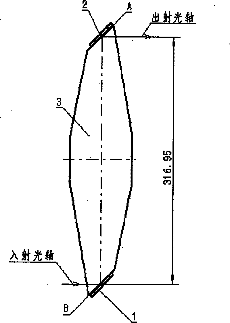
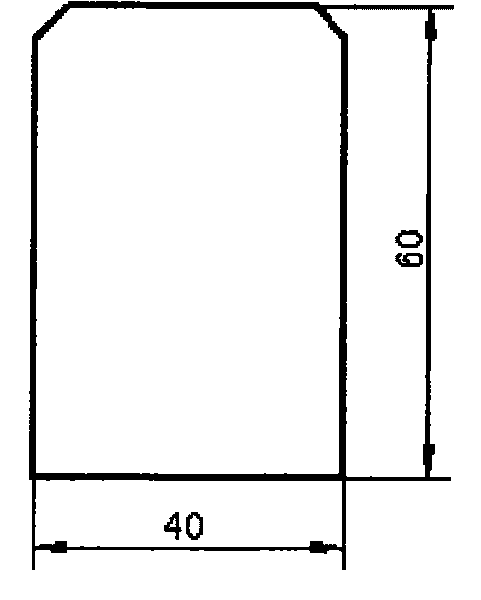
[0029] In the first step, the first and second flat mirrors 1 and 2 are processed by conventional optical parts processing technology according to the drawing requirements. The materials of the first and the second plane reflectors 1 and 2 are quartz glass, the reflective surface size is 40mm * 60mm, and the thickness is 20mm (see figure 2 ). The surface accuracy index is: N≤0.5ΔN≤0.2B≤III.

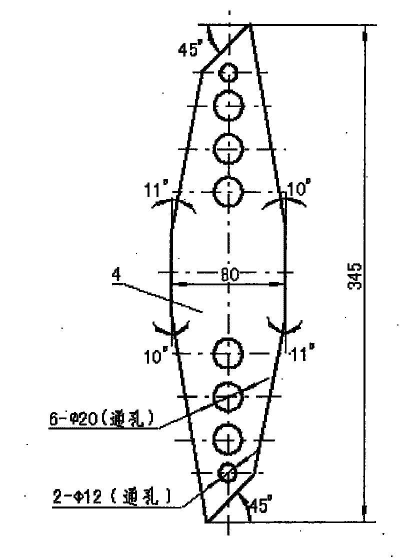
[0030] In the second step, the rectangular blank of the supporting plate 3 is formed after the quartz glass is blanked according to the conventional flow, the base is flat, and ground, and two identical rectangular blanks and the aluminum template 4 (referring to image 3 ) on ...


PUM


Abstract

The invention discloses a manufacturing method of a 180 degrees large span second parallelism of optical axis angle mirror; the substantial contents of the method are that: surface shape requirement and parallelism precision of two end surfaces of the angle mirror supporting plate are guaranteed by common optical elements processing technique; two plane reflectors are processed by adopting commonoptical elements processing technique, and sections of the reflecting surface of the two reflectors are stuck on the two end surfaces of the angle supporting plate by optical cement mode, thus formingthe angle mirror. The manufacturing method of the angle mirror in the invention not only has comparatively simple manufacturing process and shortens the manufacturing period of the angle mirror, butalso easily guarantees the second level parallelism requirement between the emergent light axis and the incident light axis, and the angle mirror has good optical cement strength and reliable quality.

Description

technical field [0001] The invention belongs to the technical field of optical cold processing, and mainly relates to a method for manufacturing a corner mirror, in particular to a method for manufacturing a corner mirror with a large-span second-level optical axis parallelism. Background technique [0002] As we all know, in an integrated optical instrument, in order to save space and make a reasonable structural configuration, it is usually necessary to bend the optical path of the optical system, and the specific bending angle depends on the specific design of the instrument. The optical element that realizes the optical path refraction of 90° generally adopts an isosceles right-angle prism and a plane reflector placed at 45° to achieve an optical path refraction of more than 90°. The corner mirror formed on the pallet is realized. The traditional 180 ° corner mirror manufacturing method is, at first, one side rough surface of the first plane reflector (or the first pris...

Claims


Application Information

Patent Timeline
Patent Type & Authority Patents(China)
IPC IPC(8): G02B5/00B24B9/14G01B11/26
Inventor 苏瑛吴乃石侯俊平叶斌张云龙郭芮刘选民
Owner CHINA NORTH IND NO 205 RES INST
Why Eureka
Try Eureka