Mounting structure for carburetor needle valve

An installation structure and carburetor technology, applied in carburetors, charging systems, machines/engines, etc., can solve problems such as high fuel consumption, unstable fuel supply, and affecting engine stability, so as to reduce fuel consumption and improve fuel supply Stable, smooth connection effect

Inactive Publication Date: 2009-03-11
CHONGQING LONCIN MOTOR
View PDF0 Cites 3 Cited by
  • Summary
  • Abstract
  • Description
  • Claims
  • Application Information

AI Technical Summary

Problems solved by technology

On the existing motorcycle carburetor, the oil needle is connected to the plunger with an M circlip, and the oil needle is prone to serial movement during use, making the gap between the conical end of the oil needle and the main nozzle fluctuate. The oil is unstable, which affects the smooth operation of the engine and leads to high fuel consumption

Method used


Image

  • Mounting structure for carburetor needle valve
  • Mounting structure for carburetor needle valve
  • Mounting structure for carburetor needle valve

Examples


Embodiment Construction

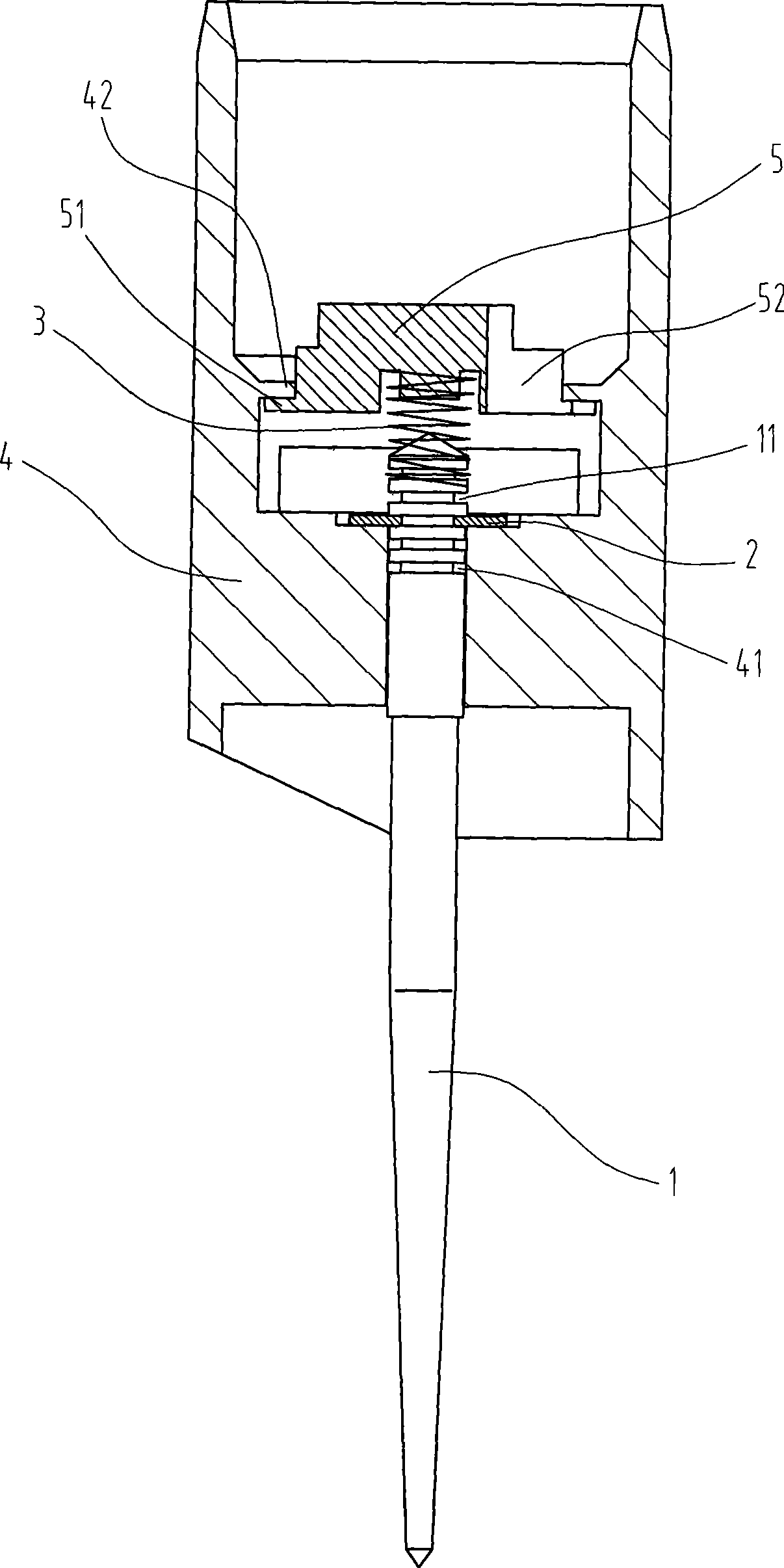
[0012] Below in conjunction with accompanying drawing and embodiment the present invention will be further described:

[0013] Such as figure 1 As shown, a carburetor oil needle installation structure is mainly used on a motorcycle flat-suction plunger carburetor. One end of the oil needle 1 is provided with a groove 11, and the other end is tapered, and the groove 11 is Clamp 2 is installed, one end of oil needle 1 with groove 11 is covered with spring 3, oil needle 1 passes through oil needle hole 41 at the bottom of plunger 4 and is limited by clamp 2, and one end of spring 3 rests on On the fixed frame 5 , the fixed frame 5 is limited by the boss 42 on the inner wall of the plunger 4 .

[0014] Such as figure 1 , figure 2 and image 3 As shown, the fixed frame 5 is tower-shaped, and there are three bosses 42 on the inner wall of the plunger 4 and are evenly distributed in the circumferential direction. Three longitudinal grooves 52 are evenly distributed in the circu...


PUM


Abstract

The invention relates to a structure for mounting an oil needle of a carburetor, which comprises a plunger and the oil needle. One end of the oil needle is provided with a groove while the other end of the oil needle is conical, a lathedog is arranged in the groove, the end of the oil needle provided with the groove is sleeved with a spring, the oil needle passes through an oil needle hole at the bottom of the plunger and is limited by the lathedog, one end of the spring is abutted against a fixed frame, and the fixed frame is limited by a lug boss positioned in the inner wall of the plunger. With adoption of the invention, the oil needle is more stably and reliably connected with the plunger so as to effectively avoid up-down movement of the oil needle in use, thereby allowing the carburetor to stably supply the oil, allowing an engine to stably operate and contributing to reduction of oil consumption of the engine.

Description

technical field [0001] The invention relates to a carburetor, in particular to a mounting structure for components on the carburetor. Background technique [0002] The common flat-suction plunger carburetor controls the intake air volume and oil output volume through the lifting movement of the plunger and the oil needle, thereby controlling the amount and concentration of the combustible mixture. The needle is a long tapered rod that controls how much fuel can be drawn into the carburetor throat. One end of the needle is attached to the plunger, and the other end is tapered and extends into the main nozzle. On the existing motorcycle carburetor, the oil needle is connected to the plunger with an M circlip, and the oil needle is prone to serial movement during use, making the gap between the conical end of the oil needle and the main nozzle fluctuate. The oil is unstable, which affects the smooth operation of the engine and leads to high fuel consumption. Contents of the ...

Claims


Application Information

Patent Timeline
IPC IPC(8): F02M19/04
Inventor 秦元伟刘贤林徐凤艳
Owner CHONGQING LONCIN MOTOR
Why Eureka
Try Eureka